I. Introduction
Planar patch antennas have been used extensively in wireless applications because of their light weight, low profile, and simple design and manufacturing [1]. A conventional patch antenna has a narrow bandwidth because of the resonance characteristic between the patch and the ground layers. Furthermore, it also has a size limitation at low frequencies, as its physical size is inversely proportional to the operating frequency [2].
A defected ground structure (DGS) can be used in patch antenna design to reduce the size of the antenna, increase the bandwidth, and improve gain by modifying the electromagnetic (EM) field distribution between the patch and the ground [3]. However, a DGS for size reduction and bandwidth increase is not generally used in patch antennas with a coaxial feed, which provides advantages for a miniaturized radio frequency (RF) module interconnection between an antenna and RF front-end circuits using via-holes [4]. A DGS patterned around a coaxial feed line or periodically patterned on a ground plane can affect the input impedance of the coaxial feed and the characteristic impedance of the transmission line on the RF module [5, 6]. These effects may increase insertion loss and deteriorate impedance matching between the antenna and the module. In addition, a DGS near the feeding line can be hidden by the ground plane of an attached RF connector, making it difficult to accurately measure antenna performance.
In this paper, a patch antenna with a coaxial feed and a DGS design that results in size reduction and bandwidth enhancement is proposed. The DGS for the proposed antenna is designed using thumb-shaped patterns, which are modifications of a rectangular DGS. The EM simulation results show that the resonant frequency of the antenna depends on the width and length of the rectangular DGS. Size reduction and bandwidth enhancement of the antenna can be achieved by altering the physical dimensions of the thumb-shaped DGS. The measurement results show that the proposed 5.8-GHz antenna implemented on an FR4 substrate achieves both an increased bandwidth and a decreased size compared with a conventional patch antenna without DGS. The design, including the EM simulation results, of the antenna with the proposed DGS and a conventional rectangular DGS is shown in Section II. The measurement results of the antenna implemented on an FR4 printed circuit board (PCB) are presented in Section III, and the bandwidth enhancement and size reduction of the proposed antenna are discussed through a comparison with previous studies. The conclusions are presented in Section IV.
II. Antenna Design
1. Patch Antenna with a Rectangular DGS
The operating frequency fr of a conventional patch antenna, in which the EM wave is evenly distributed with the ground, is determined in terms of the patch dimensions as follows:
where c is the speed of light, ɛeff is the effective dielectric constant, L is the physical length of the patch, and ΔL is the compensating term for the change in electrical length due to the EM distribution at the edge [7, 8]. The patterned ground plane from the DGS affects the EM distribution of the patch antenna. The modified frequency can be expressed using the deformed L in (1) as follows:
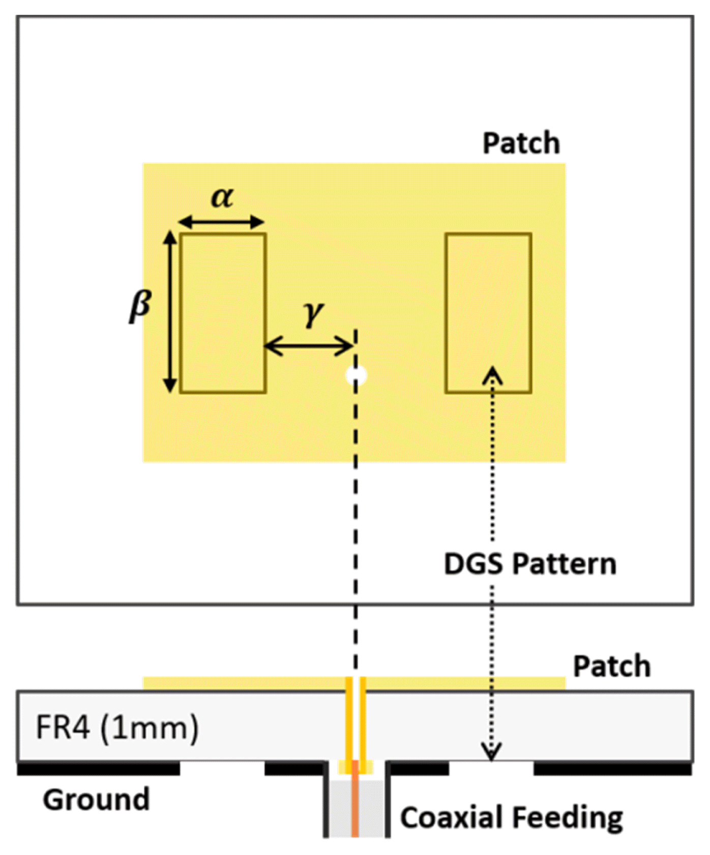
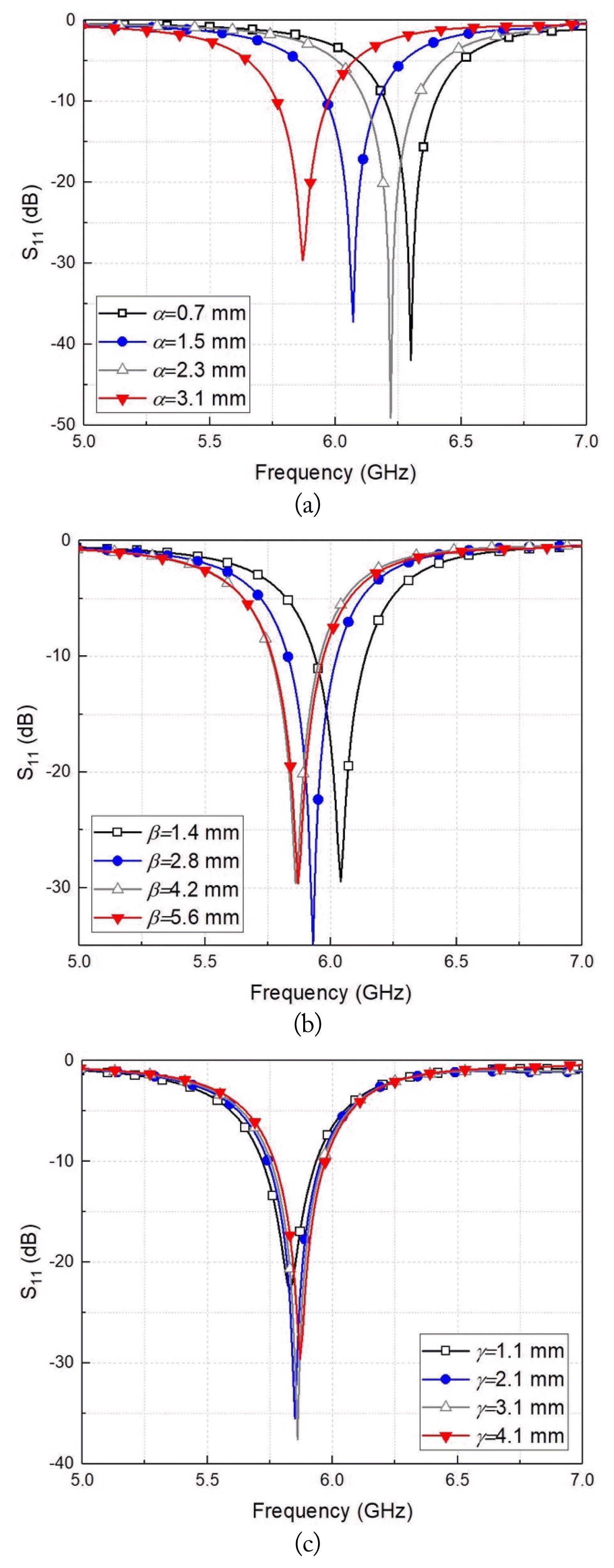
where fr_DGS is the operating frequency of the patch antenna with the DGS patterns, and LDGS is the effective length due to the EM distribution deformed by the DGS. The physical length L of the patch antenna with the same resonant frequency can be reduced because of the change in the EM distribution, depending on the shape and location of the DGS. Based on (2), a rectangular DGS with a ground pattern removed along the patch length and width affects the operating frequency and can be used to reduce the physical dimensions of the antenna because of the change in EM distribution. Considering the characteristics of the feeding point optimized for impedance matching at 5.8 GHz, the dimensions of the rectangular patch antenna (Fig. 1) are 15.4 mm × 11.5 mm. This is derived from the EM simulation using the dielectric properties of the FR4 substrate, with a thickness of 1 mm and an operating frequency of 5.8 GHz. The initial dimensions of the rectangular DGS are set to a width α of 3.1 mm, a length β of 5.6 mm, and a distance γ from the coaxial feed point of 4.1 mm for the resonance of the antenna at 5.8 GHz. Figs. 2(a) and 2(b) show that the center frequency of the antenna varies depending on the horizontal and vertical dimensions of the DGS. The center frequency decreases continuously as α increases, while the frequency shift by β converges at over 5.6 mm. The simulation results in Fig. 2(c) show that the effective length due to the DGS remains constant when the DGS pattern is positioned below the patch. The DGS under the patch can be positioned at a point where the DGS is not covered by the ground of the connector because γ, as shown in Fig. 2(c), has no significant effect on the center frequency of the antenna. The simulation results in Fig. 2 show that when operating at the desired frequency, the patch size can be reduced by placing a rectangular DGS under the patch. The frequency shift caused by the DGS is approximately 0.48 mm using the DGS, which can effectively contribute to the miniaturization of the array patch antenna. The size of the patch antenna may be reduced further as the physical dimensions (especially the α) of the DGS increase, but the design size should be optimized by considering the effect on the other characteristics, such radiation efficiency, which can be degraded by a large-sized DGS.
2. Bandwidth Enhancement Using the Proposed Thumb-shaped DGS
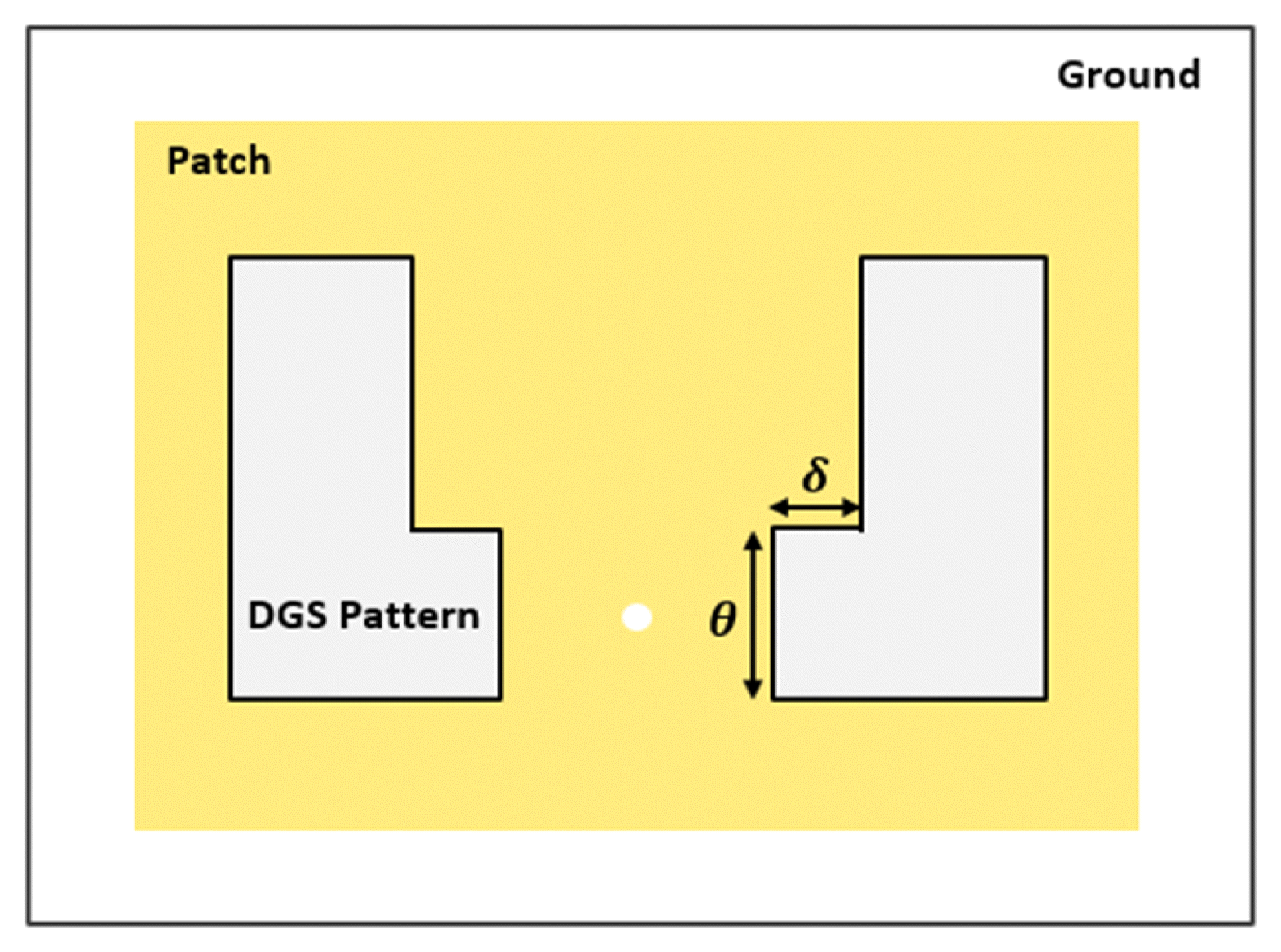
The dimensions of the patch antenna at 5.8 GHz are reduced to 15.4 mm × 10.6 mm by implementing the rectangular DGS, with α = 3.4 mm, β = 10.2 mm, and γ = 3.6 mm. However, the bandwidth of the patch antenna does not change significantly relative to the physical dimensions of the DGS, as shown in Fig. 2. The reason for this is that the DGS only alters the single resonant frequency of the antenna. A thumb-shaped DGS based on a rectangular DGS is proposed to increase the bandwidth by generating an additional resonant frequency. The resonant frequency of the patch antenna can be changed by LDGS, as expressed in (2), and the number of the frequency can be increased using various LDGS values. Fig. 3 shows the bottom view of the patch antenna with the thumb-shaped DGS, which consists of the rectangular DGS, as in Fig. 1, with an additional rectangular shape, with width and length dimensions of δ and θ, respectively. An additional shape is attached to one corner of the rectangular DGS, as shown in Fig. 3. The proposed thumb-shaped DGS is patterned symmetrically on both sides of the coaxial feed point of the antenna. When the additional LDGS generated by the proposed DGS is sufficiently smaller than the electrical length of the patch antenna shown in (2), the resonant frequencies fr1 and fr2 through the proposed DGS can be expressed as follows:
The thumb-shaped DGS consists of the rectangular DGS, as shown in Fig. 1, with an additional rectangular shape with width and length dimensions of δ and θ, respectively.
Figs. 4(a) and 4(b) show the variation in the resonant frequencies of the antenna depending on the physical dimensions of the additional shape. Both resonant frequencies and resonant characteristics change as the current flow of the DGS changes, with the low and high resonant frequencies dominantly changing by δ and θ, respectively. The frequency bandwidth, with a reflection coefficient of less than −10 dB, can be increased by designing the spacing between the two resonant frequencies.
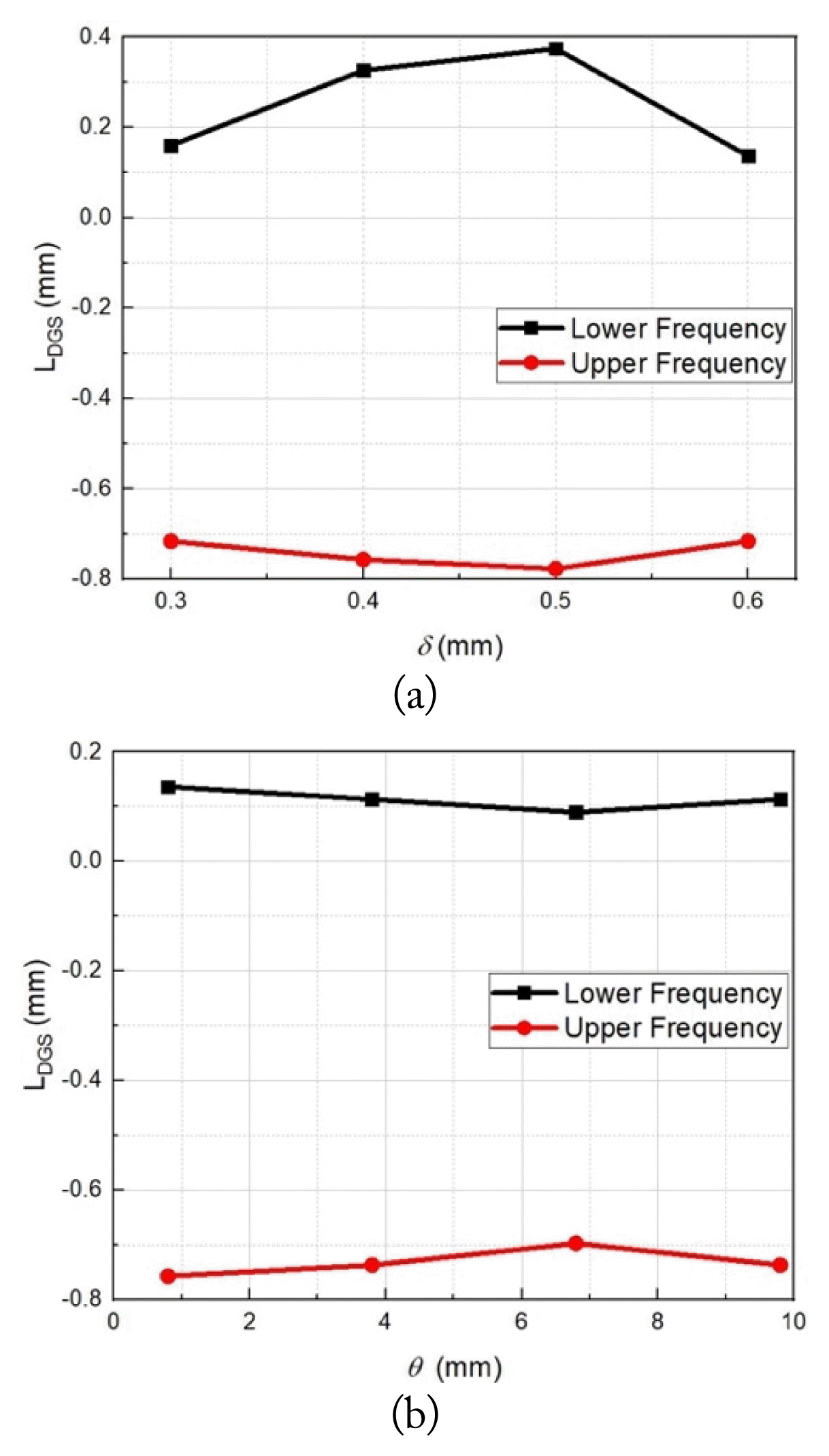
Fig. 5 shows the variations of LDGS with δ and θ. LDGS is calculated using the simulated resonant frequency changes between the antenna with the proposed DGS and the antenna with a rectangular DGS. The variations in LDGS related to the low-resonant frequency indicate that δ of the thumb-shaped pattern added to one side of the rectangular DGS directly affects the change in the effective length of the patch antenna. The high resonant frequency does not vary significantly with δ because the other side of the DGS is not changed by the thumb-shaped pattern. By contrast, θ does not significantly affect LDGS. The variation in the resonant frequency with θ is relatively small; this is consistent with the fact that the resonant frequency in the patch antenna is influenced by the length of the antenna. The maximum change (of 0.3 mm) in the LDGS due to δ shows that the effective length of the antenna can be changed by 2% depending on the δ of the proposed thumb-shaped DGS. Resonant frequency division, with respect to the proposed DGS, causes a decrease in antenna gain due to the lowering of the quality factor.
Fig. 6 illustrates the simulated current distribution on the ground plane of the patch antennas. The conventional patch antenna has a uniform current distribution on the ground plane at the bottom of the patch, as shown in Fig. 6(a). However, Figs. 6(b) and 6(c) reveal that the current distribution of the patch antenna with DGS patterns increases around the patterns. The change in the current distribution indicates that the electrical length of the patch antenna can be varied by the DGS. The current distribution on the ground plane of the antenna with the proposed DGS patterns is asymmetrical, and the formation of various electrical lengths by the asymmetric distribution can split the resonant frequency to increase the bandwidth of the antenna. Compared with a rectangular DGS, the high current density around the proposed DGS indicates that the electrical length can be effectively changed by the proposed DGS. The dimensions of the 5.8-GHz patch antenna are further reduced to 15.0 mm × 10.6 mm by the thumb-shaped DGS patterns. The patch length, resonant frequency, and fractional bandwidth of the antennas, depending on the use of the DGS, are summarized in Table 1. Fig. 7 shows the simulated bandwidth and resonant frequency for performance comparison among the designed patch antennas.
III. Measurement Results
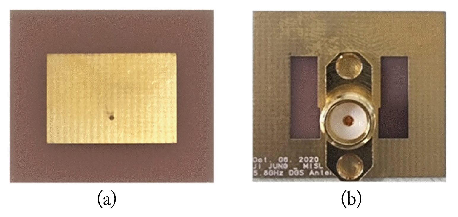
The proposed antenna is designed to have a bandwidth enabling operation at 5.8 GHz, even when the center frequency is offset due to the resolution of the PCB fabrication process. The final dimensions of the additional shape of δ and θ are 0.3 mm and 3.8 mm, respectively, as shown in Fig. 8. The patch size at the 5.8 GHz antenna with the proposed thumb-shaped DGS is reduced by 10.2% from 177.1 mm2 to 159.0 mm2. The coaxial feed of the antenna is implemented by inserting a signal terminal of an RF connector into the via-hole of the feed point.
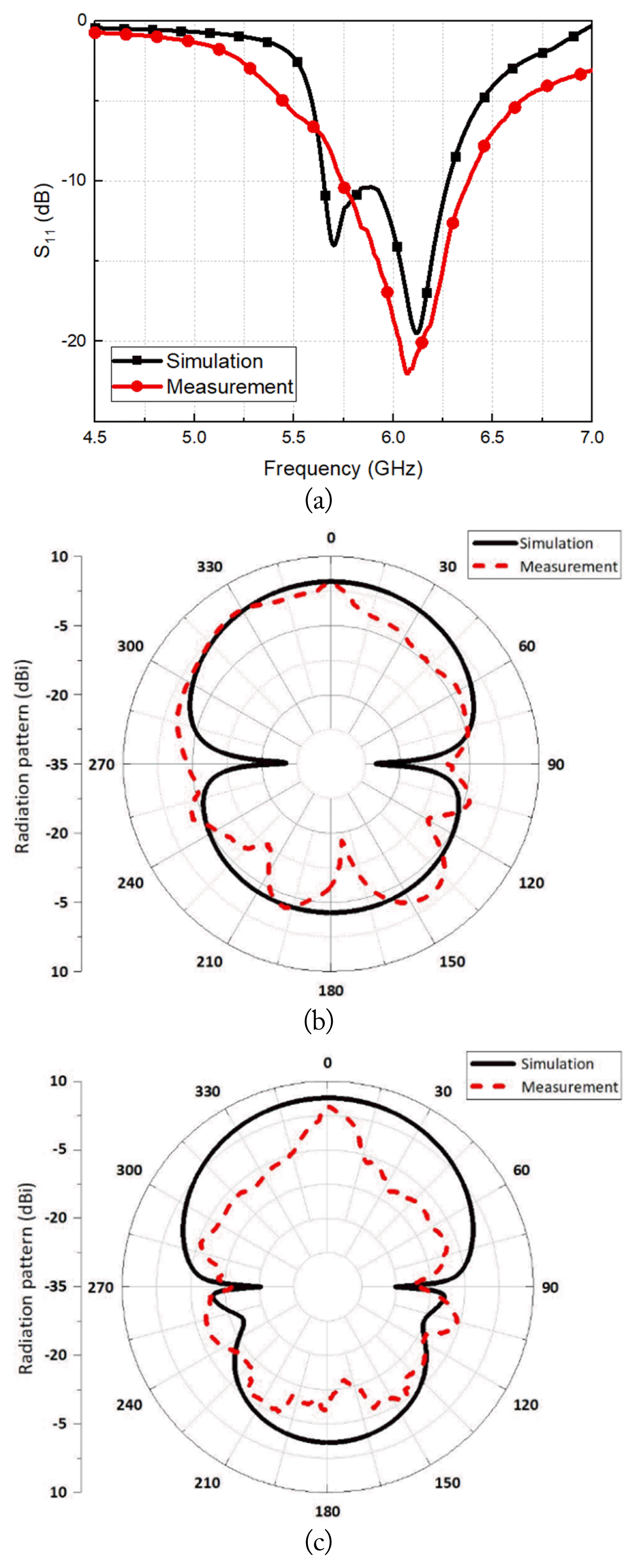
Fig. 9 shows the simulation and measurement results of the proposed 5.8-GHz antenna. The measured center frequency shift is higher than the simulated frequency, but the desired frequency of 5.8 GHz is located within the −10 dB bandwidth, even with the frequency shift. The reflection coefficient of the proposed antenna is −12 dB at 5.8 GHz, as shown in Fig. 9(a). The high resonant frequency is almost the same as that in the simulation, but the measured low-resonant frequency shifts up compared with that of the simulation. The frequency shift is caused by the PCB tolerance that affects δ, which dominantly determines the low-resonant frequency in the thumb-shaped DGS. The frequency bandwidth of the proposed antenna is 580 MHz, which is 3.22 times higher than that of the antenna without DGS. The measured antenna gain is 4.4 dBi from the radiation patterns in Figs. 9(b) and 9(c). The difference in the radiation patterns between the simulation and the measurement results is caused by the influence of the dielectric jig placed vertically to secure the antenna during the measurement setup.
Table 2 summarizes the performance comparison between the proposed antenna and previous studies using DGS designed at an operating frequency near 5.8 GHz. The fractional bandwidth of the proposed antenna is improved to 10%, compared with approximately 5% of the previous antennas. The gain of the proposed antenna is lower than those reported by previous studies, and it has the disadvantage of improving antenna gain. The area effective ratio (AER) is proposed as an index for comparing the patch size per unit area relative to the operating frequency of the antenna and is defined as follows:
where λ is the free-space wavelength at the operating frequency, ɛr is the dielectric constant of the PCB substrate, and Apatch is the patch area of the antenna. The AER of the proposed antenna, which is the highest value in Table 2, shows that the patch size is effectively reduced compared with the previous antennas. The AER of the proposed antenna, which is the highest value in Table 2, shows that the patch size is effectively reduced compared with the previous antennas.
IV. Conclusion
A 5.8-GHz coaxial feed patch antenna with a thumb-shaped DGS is proposed to simultaneously achieve bandwidth increase and patch size reduction. The thumb-shaped DGS with an additional rectangular shape protruding from one side of the rectangular DGS, which is useful for reducing patch size, can improve bandwidth by generating two resonant frequencies. The measurement results of the 5.8-GHz antennas implemented on an FR4 PCB substrate show that the proposed antenna can effectively reduce the patch size and increase the fractional bandwidth by a factor of two compared with previous studies. The proposed antenna and thumb-shaped DGS can be effectively used to implement a unit antenna constituting a planar-type large-scale antenna array for a phased array system.