 |
 |
- Search
| J. Electromagn. Eng. Sci > Volume 22(3); 2022 > Article |
|
Abstract
The design of television (TV) antennas for commercial use that operate on the ultra-high frequency (UHF) band has become more challenging given the relatively large size of these antennas and considering that they typically do not conform to aesthetically pleasing standards. This paper presents a transparent liquid multiple-antenna array for ultra-high-definition TV (UHD TV) applications (470–770 MHz; 48.5%). The motivation behind the use of multiple antennas is that a single transparent antenna normally performs poorly given the low conductivity of transparent conductors. The multiple-antenna array here consists of two saltwater antenna elements with high optical transparency (>90%). The antenna elements are organized in three working modes to achieve higher gain and omnidirectional characteristics. Experimental results find that the antenna in array mode shows a high gain of up to 5.27 dBi in the UHF band, while the diversity mode shows various beam patterns with good diversity gain outcomes. These results demonstrate the potential of the proposed multiple-antenna array to increase the reception rate of UHD TV applications.
Currently, digital television (DTV) is highly attractive for applications in ultra-high definition (UHD) due to the advantages of a high-data-rate transmission and interactive services [1–2]. Designing an antenna for such applications requires not only a wide operating bandwidth (BW) to cover the DTV band fully but also a guarantee of high performance within a limited design [3]. To meet these requirements, the use of a small internal antenna that can be integrated into the mainboard or on the edge of the TV represents a good approach. However, the design of such internal antennas is difficult because most current TVs are very slim with highly limited internal space. Moreover, internal antennas will be influenced by other electrical parts, which can reduce their performance capabilities [4]. Owing to these concerns, the design of a high-performance external antenna is preferred for implementation as a TV antenna. However, the dimensions of antennas are related to the wavelength of the operating frequency; therefore, antennas operating on the ultra-high frequency (UHF) band are usually large, which limits their use [5]. To overcome this problem, we propose the use of an external antenna with high optical transparency (OT), installable on the frame of a TV, thus eliminating many conformity and aesthetic issues.
In recent years, optically transparent antennas have attracted significant attention in both theoretical research and practical applications due to their unique ability to be integrated onto the surfaces of other items with almost complete transparency, while also not affecting the appearance of the product [3], [6–9]. At present, most existing transparent antennas use a solid metallic transparent electrode (TE), such as indium tin oxide (ITO) [3, 6], multilayer film (MLF) [7–8], or a metal mesh (MM) [9], as a conductive material. However, an MM or MLF, such as the IZTO/Ag/IZTO and AgHT types, have relatively low OT in the visible band. On the other hand, ITO has a higher OT but is expensive due to the cost of the rare-earth indium component.
More recently, saltwater, given its excellent OT (> 95% at salinity 40 parts per thousand [ppt]), has been considered a potential transparent conductor with which to create a new class of high-transparency antennas [10–15]. In a previous work [10], a seawater monopole antenna with high efficiency for WLAN applications was presented, and another work [11] presented a pattern-reconfigurable circular monopole with parasitic water reflectors that enables beam steering for maritime applications. Other saltwater antennas were also proposed and studied for different practical applications [12–15]. However, the most difficult aspect when designing a saltwater antenna is accounting for the low conductivity of saltwater. Therefore, most existing saltwater antennas use a cylindrical structure to improve both the sheet resistance and radiation efficiency [10–15]. A cylindrical shape allows light to arrive at the antenna not only at normal but also at oblique incidence angles. Therefore, strong reflection and refraction occur, reducing the antenna transparency. This makes the design of saltwater antennas capable of high OT and good electrical performance a continuing challenge for practical applications.
In this paper, we proposed the use of multiple transparent liquid antennas for UHD TV applications. The justification for using multiple antennas is that a single transparent antenna normally performs poorly because transparent conductors have low conductivity. The multiple antennas structure consist of two liquid monopoles as antenna elements. The monopole antenna using saltwater is held in a hollow L-shaped clear acrylic material as a conductive part, with a 50-inch TV cover used in this case as a ground plane. The proposed structure can avoid the reflection and refraction of light associated with cylindrical structures. Moreover, the proposed multiple-antenna structure can work under three modes that are interchangeable to achieve omnidirectional characteristics and improve the gain of the antenna array. In this way, the multiple antennas here have high gain with an omnidirectional radiation pattern, or they achieve radiation pattern diversity suitable for UHD TV applications.
First, we briefly present the electrical and optical characterization of saltwater as a conductor in the design of the antenna. Second, the design of a single transparent liquid antenna using saltwater is presented, and a simulation is conducted to understand the behavior of the liquid antenna. Finally, two different multiple-liquid-antenna configurations are proposed to achieve higher gain and radiation pattern.
Fig. 1 shows the measured conductivity and OT of saltwater at various salinity levels, from 35 to 200 ppt. Conductivity is measured by a portable electrical conductivity meter (model HI8633, Hanna Instruments Co., US), while the OT in the visible band is measured using a UV/VIS spectrophotometer (T60 model, PG Instruments Limited Co., UK) connected to a computer.
As shown in Fig. 1, the conductivity increases rapidly, while the OT decreases slightly with increases in salinity. It should be noted that the maximum salinity level at room temperature is 263 ppt. Saltwater with a salinity of 200 ppt shows efficient conductivity of 20 S/m while maintaining an extremely high average OT of 91.5%. Therefore, we use saltwater with a salinity of 200 ppt in the antenna design to reduce the ohmic loss of the antenna.
Fig. 2 shows the geometry of the single transparent liquid antenna mounted on the upper edge of a 50-inch TV cover. As shown in Fig. 2(a), the antenna is located at the x-coordinate of d, and the position of the antenna can be moved along the x-axis. Positive and negative d values correspond to the antenna position located at the left and right sides of the z-axis, respectively. Fig. 2(b) shows a closer view of the antenna geometry with the dimensions. Clear hollow L-shaped acrylic (ɛ = 2.6, tanδ = 0.01) is used to hold the saltwater, which is fed by an SMA connector. Fig. 2(c) shows an actual photo of the fabricated antenna over text, demonstrating that excellent OT is achieved. Because a saltwater antenna has poor radiation efficiency due to the saltwater’s ohmic loss, the dimensions of the antenna are optimized in this study to attain the maximum efficiency rates. In the parametric analysis, L1 is varied so the total length of the antenna (L1+L2) equals a quarter wavelength at the UHF band’s center resonance frequency of 600 MHz; therefore, there are three key parameters that most affect the antenna’s performance, including W1, W2, and L1. As shown in Fig. 3, when L1 increases from 20 to 100 mm, the efficiency increases dramatically. More specifically, as L1 increases from 20 to 50 mm, the antenna’s effectiveness increases rapidly, followed by steady increases as L1 exceeds 50 mm. An increase in L1 results in a larger overall volume of the antenna for the TV model, even though the total length of the antenna remains unchanged. As a result, the ideal value for L1 is 50 mm. As shown in Figs. 3(b) and (c), the radiation efficiency of the antenna increases to the maximum value and then decreases when W1 and W2 increase. The maximum radiation efficiency is achieved at W1 = 40 mm and W2 = 20 mm. Finally, the optimum dimensions of the antenna for the simulation and fabrication are listed in Table 1. It should be noted that a is the thickness of the antennas (not shown in the schematic).
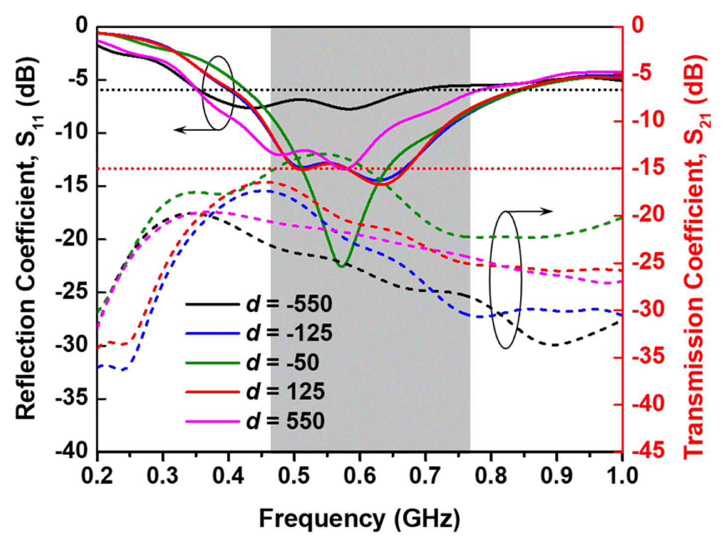
Fig. 4 shows the simulated performance of the single antenna mounted on the UHD TV cover as the ground plane. It should be noted that the ground plane is much larger than the antenna and will therefore greatly impact the antenna performance [5]. The simulated performance capabilities of the single antenna in terms of the impedance-matching level, gain, and radiation pattern are investigated at various locations of the antenna on the upper edge of the TV cover. As shown in Fig. 4(a), the input impedance matching of the antenna becomes poorer when it moves from the center to the leftmost/rightmost areas of the TV cover. To ensure a 6-dB bandwidth that fully covers the UHF band (470–771 MHz), the antenna must be located within a distance of 350 mm from the center. Moreover, Fig. 4(b) indicates that the average realized gain increases significantly when the antenna moves from the center to the left/right sides of the TV cover. However, the gain increases significantly slower when it moves close to the leftmost and rightmost sides. We also investigate how the radiation pattern of the antenna changes when it moves from the leftmost area (d = −550) through the center (d = 0) to the rightmost area (d = 550) of the TV cover. As shown in Fig. 4(c), when the antenna is located at the center of the TV cover, it shows an omnidirectional radiation pattern. However, when it moves to the leftmost and rightmost sides of the TV cover, the radiation pattern of the antenna changes to a directional pattern. It should be noted that broadcast applications, such as TV, generally require an omnidirectional antenna to increase the reception rate. Therefore, the single antenna, when located at the left or right side of the TV cover, will reduce the reception rate of the UHD TV. To overcome the trade-off between the gain and omnidirectional radiation pattern requirement of the single antenna, we propose the use of a multiple-antenna configuration. The investigation of the multiple liquid antennas will be presented in the next section.
Multiple antennas are proposed for communications systems due to the considerable advantages they provide in terms of better communication reliability and greater channel capacity levels. Therefore, we propose the use of a multiple-antenna configuration to overcome the disadvantages of the aforementioned single antenna. The proposed multiple-antenna configuration consists of two identical liquid antennas mounted on the upper part of a 50-inch TV cover as the ground plane. The dimensions of the antenna element are identical to those of the single antenna presented in Table 1.
Fig. 5 describes the three working modes of the multiple antennas that are used to increase the reception rate of UHD TV applications. As shown in Fig. 5, two identical liquid antennas, referred to here as ANT 1 and ANT 2, are located at the x-coordinate of d and −d, respectively. The multiple antennas can work under three different modes. At mode 0, two antenna elements use a common feeding source and a power divider to connect the source to each element. Due to the symmetry of the array antenna configuration, we expect to achieve an omnidirectional radiation pattern and an improvement in the peak gain. In the diversity configuration (mode 1 and mode 2), we used two separate sources to excite the antenna elements. The two antenna elements work independently, and because they have different radiation patterns (see Fig. 4[c]), good beam diversity is expected to be achieved with this configuration, which can also improve the reception rate of the UHD TV. The three working modes can be interchanged so that the selected mode receives the strongest incident signal. With the combination of the diversity gain (DG) and the array gain, we expect that the reception rate of the UHD TV can be improved. In the next analysis, we investigate the performance of the multiple antennas in array (mode 0) and diversity configurations (modes 1 and 2) in a stepwise manner with different spacings between the two antennas.
Fig. 6 shows the simulated performance outcomes of the array liquid antenna (mode 0) with distinct locations of the antenna elements. The array antenna exhibits an impedance matching trend similar to that of the single antenna, while the impedance matching becomes poorer when the antennas move to the leftmost and rightmost areas of the TV cover (Fig. 6[a]). As expected, the array antenna shows a higher average realized gain on the UHF band compared to the single antenna (Fig. 6[b]). The average gain of the array antenna increases slightly when the two antenna elements move from the center to the left and right sides of the TV cover. Fig. 6(c) shows the 3D radiation patterns of the array antenna when the two antenna elements are located far from each other (at the leftmost and rightmost sides) and close to each other (d = −50). We can observe an omnidirectional radiation pattern of the array antenna with any position of the antenna elements owing to the symmetric structure of the array antenna. This type of radiation pattern is suitable for broadcast applications, such as reception TV.
Fig. 7 shows the S-parameter of the multiple diversity antennas (modes 1 and 2) at different positions of the antenna elements. It was found that the resonant frequency of the antennas moves slightly to the lower band and that the impedance matching becomes poorer when the two elements move from the center to the leftmost and rightmost of the TV cover. It was also found that to ensure that the resonance band fully covers the UHD TV band, the antenna must be located within the range of −360 to 360. Moreover, to maintain the mutual coupling level between the two antenna elements below −15 dB, each element must be separated by at least 105 mm from the center of the TV cover.
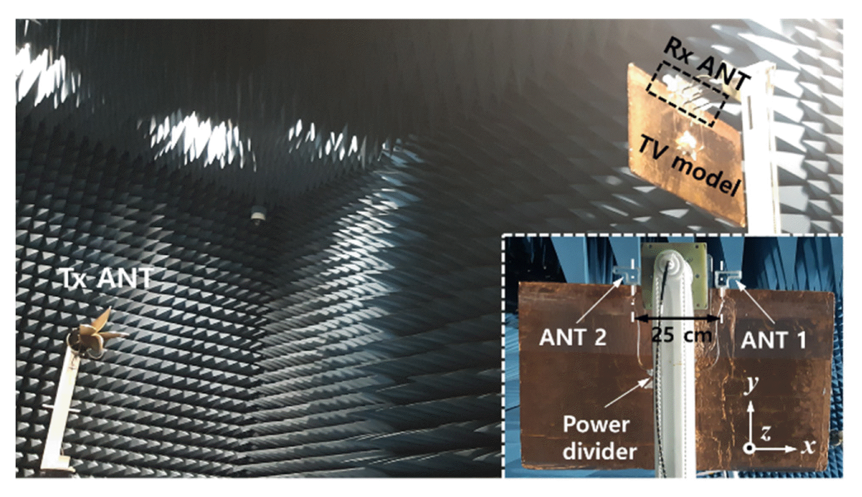
In this section, the performance of the liquid multiple-antenna configuration will be experimentally assessed to confirm its potential for UHD TV applications. For this experiment, two transparent liquid antennas are fabricated and mounted on a 50-inch TV cover (600 mm × 1,100 mm) as the ground plane. Fig. 8 shows the measurement setup of the fabricated multiple antennas in an anechoic chamber. The inset image in Fig. 8 depicts the detailed configuration of the multiple-liquid-antenna configuration, where the two liquid antenna elements are separated by an inter-element distance of 25 cm corresponding to a half-wavelength at the center frequency of the UHF band.
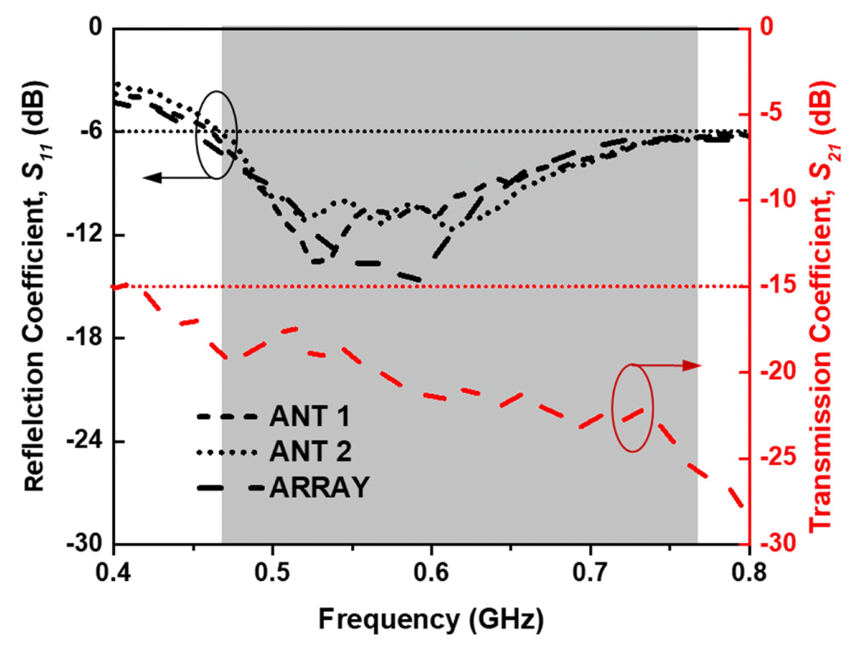
Fig. 9 shows the measured S-parameters of the array antenna (mode 0) and the two antenna elements (modes 1, 2). These assessments were conducted using a vector network analyzer (model E5071B). The first antenna element (ANT 1) shows a 6-dB bandwidth from 462 MHz to 775 MHz (313 MHz; 50.6%), while the second element (ANT 2) operates at nearly the same frequency band as the first, with a 6-dB bandwidth from 465 MHz to 776 MHz (311 MHz; 50.1%). The measured reflection coefficient of the array antenna shows a 6-dB bandwidth from 460 MHz to 773 MHz (313 MHz; 50.8%). The measurement results of the array antenna and the two antenna elements confirm that the working frequency band of multiple antennas in the three modes fully covers the UHF band for UHD TV applications from 470 to 771 MHz (301 MHz; 48.5%). Meanwhile, the transmission (isolation) coefficient between the two antenna elements in mode 0 is below −15 dB, demonstrating that the two antennas are well isolated.
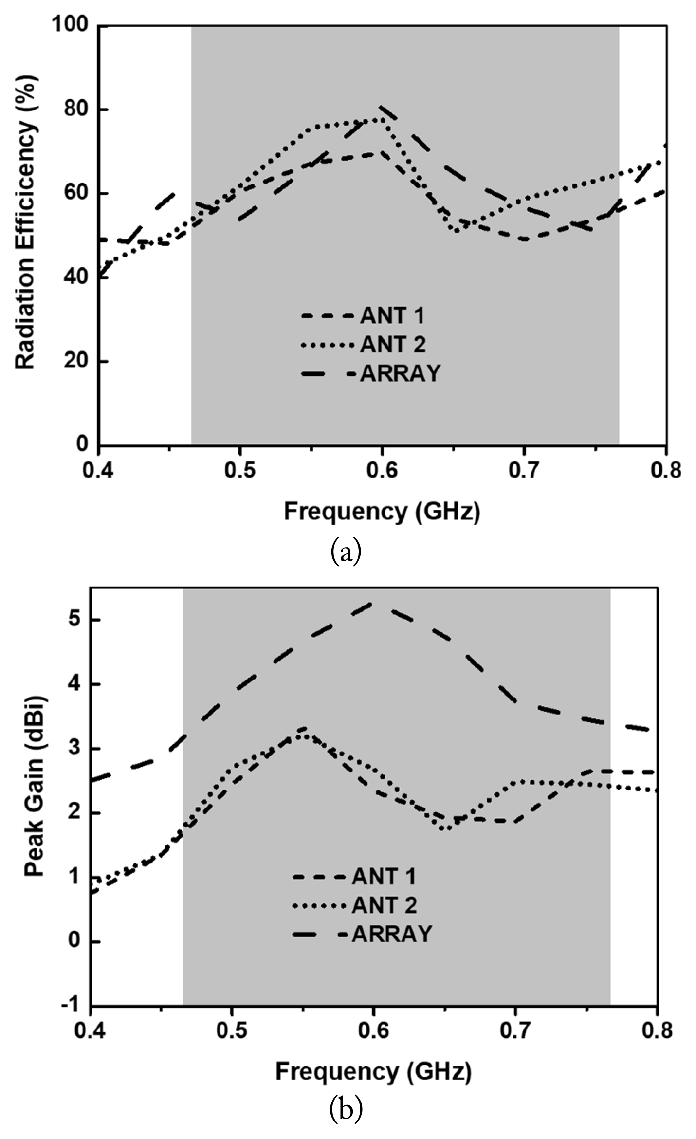
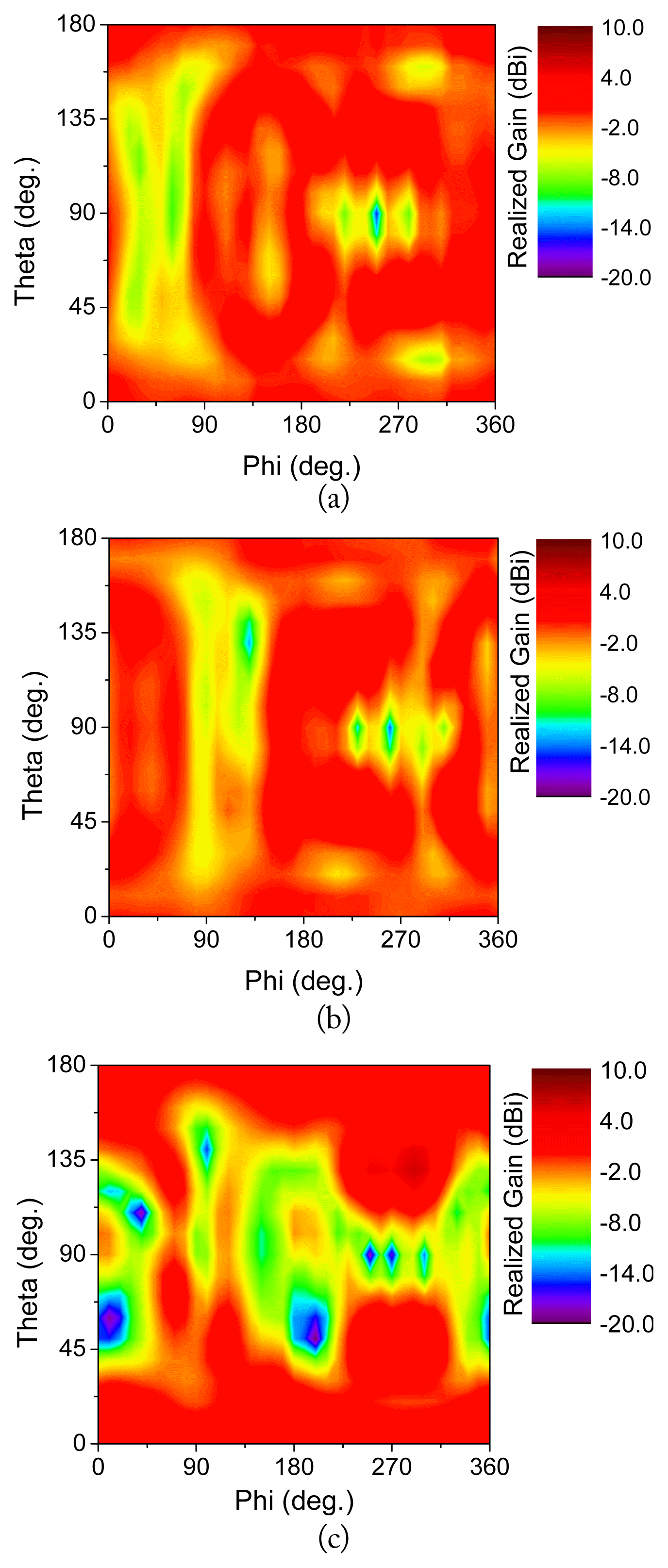
The radiation efficiency rates and peak gains of the multiple-antenna configuration are assessed by far-field measurements in an anechoic chamber, as shown in Fig. 10(a). Both the array and diversity configurations show typical radiation efficiency rates on the operating band. The average efficiency rates of ANT 1, ANT 2 (diversity configuration), and the array antenna (array configurations) on the UHF band are 62.3%, 65.1%, and 66.2%, respectively. Fig. 10(b) shows the measured peak realized gain of the multiple-antenna array in both configurations. As expected, the array antenna shows a significantly high gain on the UHF band up to 5.27 dBi, with an average value of 4.12 dBi on this band, while the average peak gains of ANT 1 and ANT 2 in this band are 2.35 dBi and 2.41 dBi, respectively. To confirm the proper beam diversity of the multiple antennas, the gains of the antennas in the three working modes are measured at all directions, with angle theta (θ) from 0 to 180° and angle phi (ϕ) from 0 to 360°. As shown in Fig. 11, the null directions of ANT 1 and ANT 2 occur in different zones of the ϕ values; therefore, the null direction can be avoided by the interchange between ANT 1 and ANT 2 when the received signal comes from different directions.
Moreover, the array antenna (mode 0) shows the main lobe with a significantly high gain in the zone, with 0 ≤ θ ≤ 40° and 140° ≤ θ ≤ 180°, which can be used to replace the diversity antennas (modes 1 and 2). Overall, the measurement results in Fig. 11 confirm that upon an interchange among the three working modes, the multiple antennas can avoid the null directions to achieve an omnidirectional radiation pattern for all directions of the incident signal.
Finally, the measured performance outcomes of the single and multiple antennas in terms of the gain and radiation efficiency are summarized in Table 2 for comparison. The DG of the multiple antennas is also assessed to confirm the diversity of the antennas. The DG is calculated using Eq. (1) [16].
where ECC is the envelope correlation coefficient, which is defined from the S-parameter via Eq. (2).
Table 3 shows a performance comparison between the proposed antenna and other transparent antennas. Most of the antennas that are reported in [10], [11], [17], and [18] are saltwater antennas, while the antenna in [3] uses solid MM as its conductor part. We can observe that the liquid transparent antennas show higher OT than the solid antenna. However, the liquid antennas have lower radiation efficiency than the solid due to its lower conductivity. Among the antennas, the proposed antenna shows a highest transparency and highest gain due to the use of a rectangular prism structure and an array structure, respectively.
In this paper, we presented multiple transparent liquid antennas for UHD TV applications. The multiple antennas include two monopole antenna elements made from saltwater at a high concentration working under array and diversity configurations to meet the requirements for a high signal reception rate in TV devices. The inter-element distance between the antennas is set to a half-wavelength of the center frequency of the band. The measurement results show that the proposed antennas have a significantly high OT, exceeding 90% on the visible band. The array antenna shows a high gain of up to 5.27 dBi, with an average gain of 4.12 dBi on the UHF band, while the antenna elements in the diversity configuration show a sufficient average gain. Moreover, the beam diversity of the multiple antennas is confirmed by measurements. In terms of efficiency, the multiple-antenna configuration shows a slight improvement compared to the single antenna, which is acceptable for practical broadcast applications, such as UHD TV.
Acknowledgments
This study was supported by the Research Program funded by Seoul National University of Science and Technology.
Fig. 1
Measured conductivity (black dots) and optical transparency (OT; red dots) of saltwater corresponding to different salinity levels at room temperature.

Fig. 2
Geometry of the single liquid antenna implemented in a 50-inch UHD TV model: (a) overall view, (b) closer view showing the dimensions of the antenna, and (c) fabricated transparent liquid antenna over text.
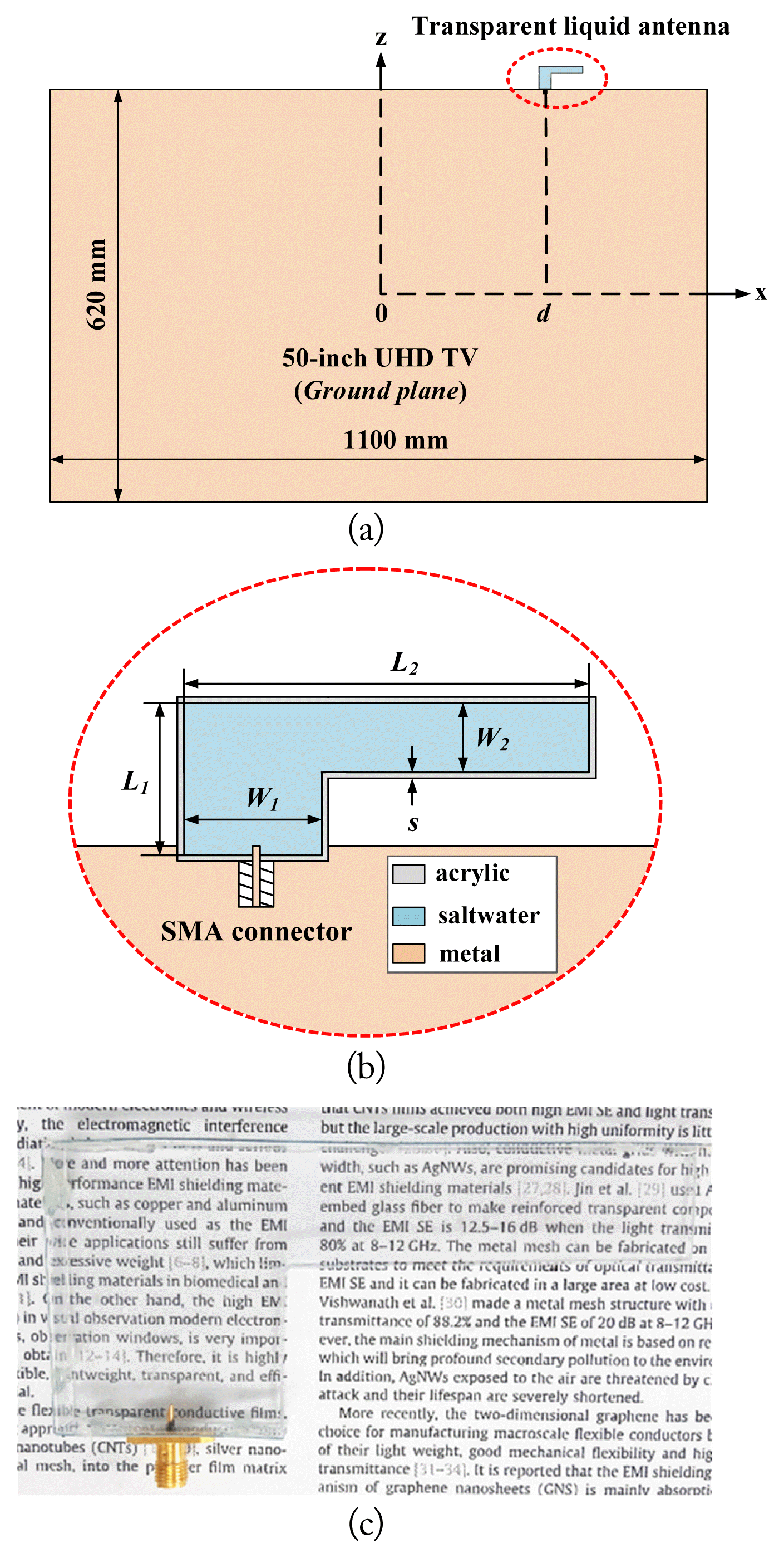
Fig. 3
Average radiation efficiency of the proposed single antenna in the UHD TV band versus different geometric antenna parameters: (a) L1, (b) W1, (c) W2.
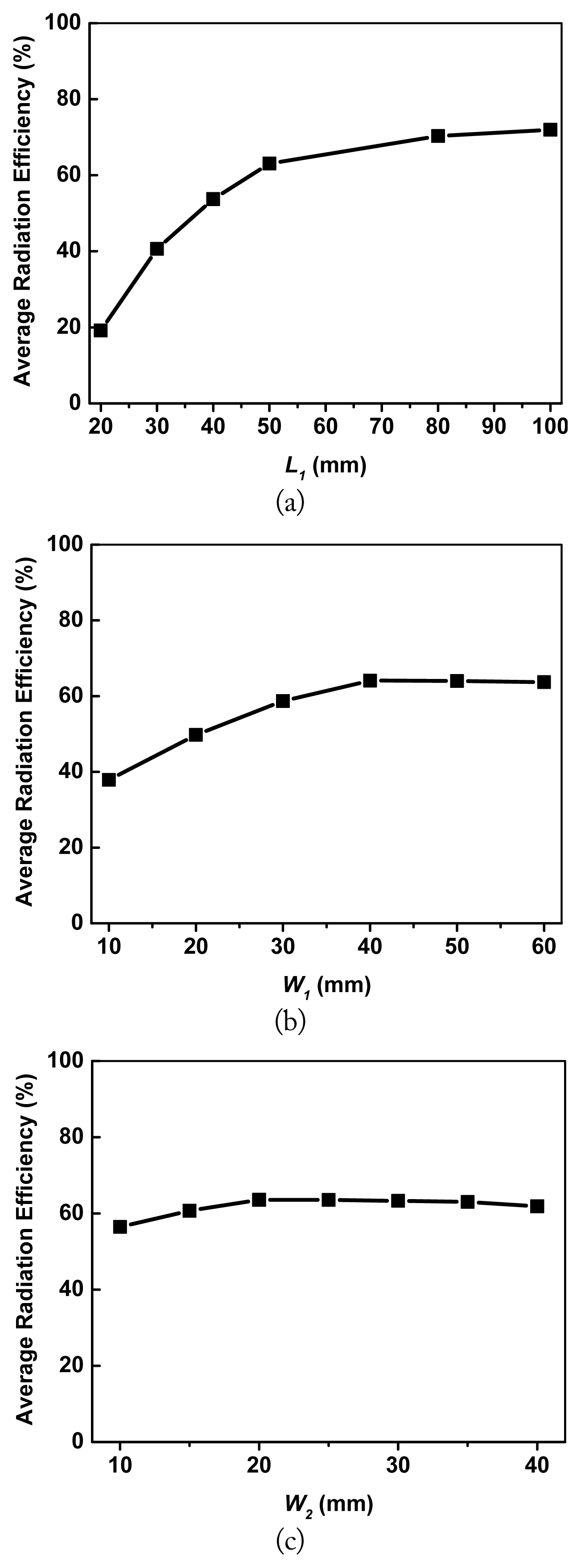
Fig. 4
Simulated performance of the single liquid antenna at various positions on the upper edge of the UHD TV: (a) reflection coefficients, (b) average realized gain in the UHF band, and (c) 3D radiation pattern
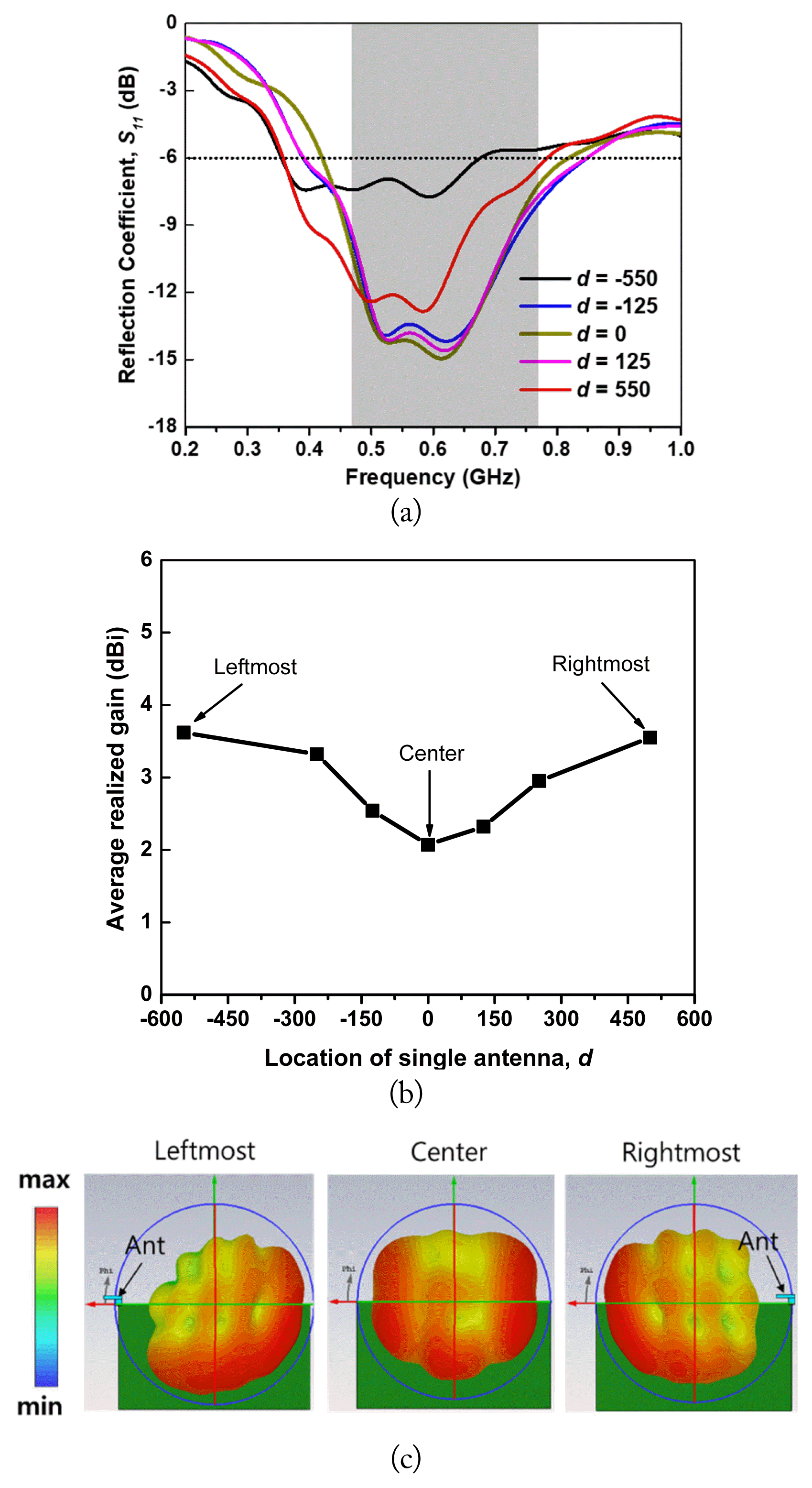
Fig. 5
Schematic of multiple liquid antennas mounted on a UHD TV as the ground plane describing three working modes.
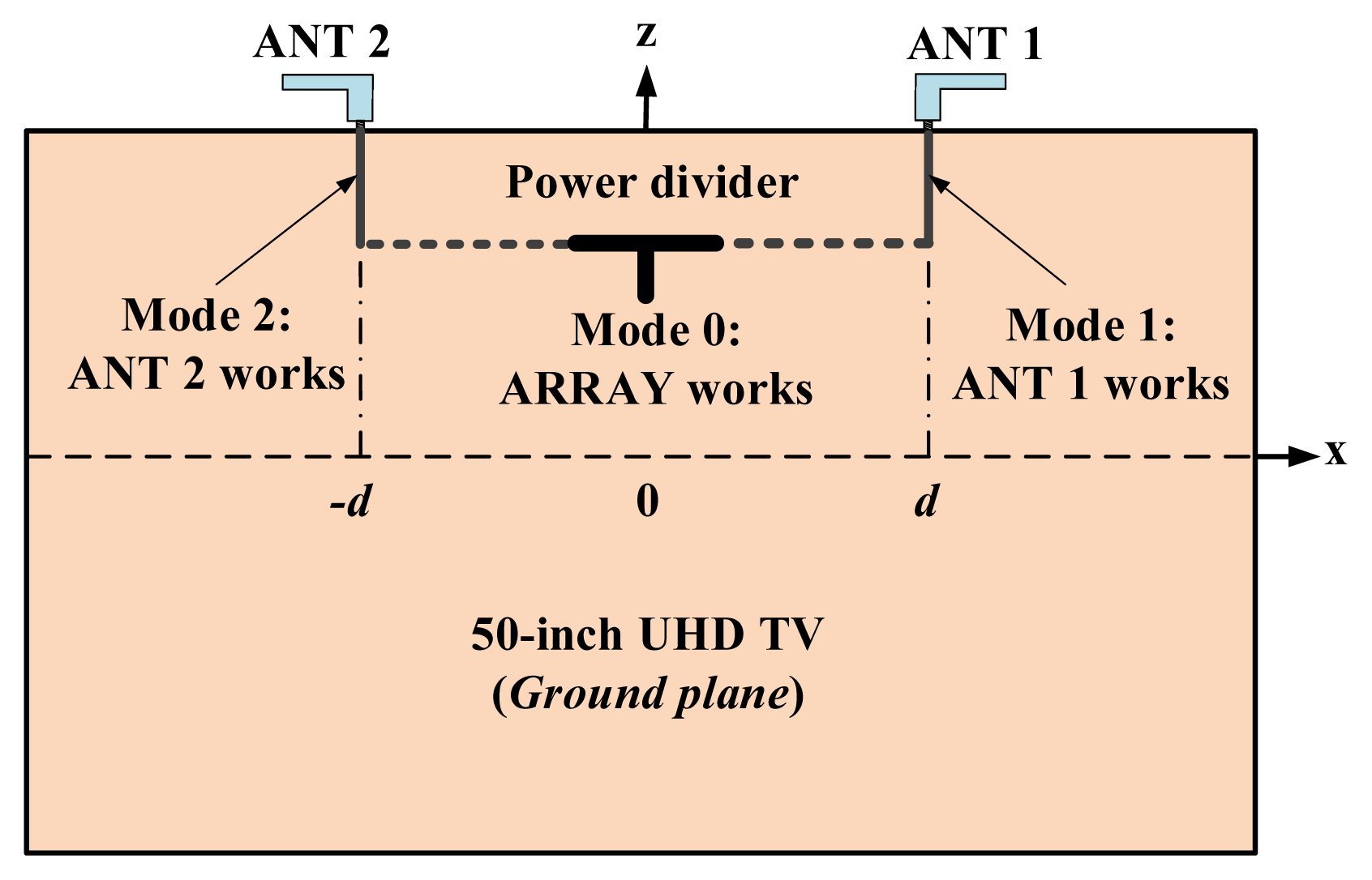
Fig. 6
Simulated performance of the liquid array antenna with different distances between the two antenna elements: (a) reflection coefficient, (b) average realized gain in the UHF band, and (c) radiation pattern.
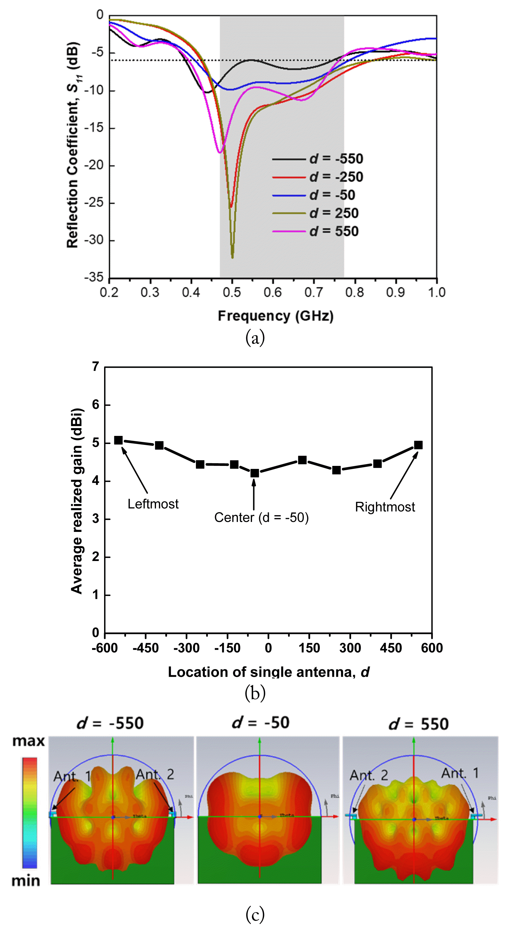
Table 1
Dimensions of the Single Liquid Antenna
| Parameter | L1 | L2 | W1 | W2 | s | a |
|---|---|---|---|---|---|---|
| Value (mm) | 50 | 80 | 40 | 20 | 1 | 10 |
Table 2
Performance Capabilities of Single and Multiple Antennas
Table 3
Performance comparison between the proposed antenna and previous transparent antennas
| Ref. | Relative BW (%) | Gain (dBi) | Rad. Eff. (%) | OT (%) | Structure |
|---|---|---|---|---|---|
| [3] | 54.5 | 2.4 | 72.1 | 68 | Planar |
| [10] | 41.5 | 2.3 | 72 | 85 | Cylinder |
| [11] | 37.5 | 5 | 60 | N/A | Cylinder |
| [17] | 35.5 | 4.5 | 56.5 | N/A | Cylinder |
| [18] | 73.3 | 1 | 60 | N/A | Cylinder |
| This work | 50.8 | 5.27 | 66.2 | 91 | Rectangular Prism |
References
1. YH Park, J Kim, M Kim, W Lee, and S Lee, "Programmable multimedia platform based on reconfigurable processor for 8K UHD TV," IEEE Transactions on Consumer Electronics, vol. 61, no. 4, pp. 516–523, 2015.

2. CJ Wang and YL Lee, "A compact dipole antenna for DTV applications by utilizing L-shaped stub and coupling strip," IEEE Transactions on Antennas Propagation, vol. 62, no. 12, pp. 6515–6519, 2014.

3. TD Phan and CW Jung, "Optically transparent wideband dipole and patch external antennas using metal mesh for UHD TV applications," IEEE Transactions on Antennas Propagation, vol. 68, no. 3, pp. 1907–1917, 2020.

4. S Shinde, X Gao, VV Khilkevich, and D Pommerenke, "Modeling EMI due to display signals in a TV," IEEE Transactions on Electromagnetic Compatibility, vol. 58, no. 1, pp. 85–94, Feb;2016.

5. TV Trinh, T Park, and CW Jung, "Internal fork-shaped wideband monopole antenna with a parasitic sleeve for ultra-high-definition television applications," Microwave and Optical Technololy Letters, vol. 61, no. 12, pp. 2725–2729, Dec;2019.


6. G Sun, B Muneer, and Q Zhu, "A study of microstrip antenna made of transparent ITO films," In: 2014 IEEE Antennas and Propagation Society International Symposium (APSURSI); Memphis, TN. pp 1867–1868, 2014.

7. S Hong, Y Kim, and CW Jung, "Transparent microstrip patch antenna with multilayer and metal-mesh films," IEEE Antennas and Wireless Propagation Letters, vol. 16, pp. 772–775, 2017.
8. MSA Rani, SKA Rahim, MR Kamarudin, T Peter, SW Cheung, and BM Saad, "Electromagnetic behaviors of thin film CPW-fed CSRR loaded on UWB transparent antenna," IEEE Antennas and Wireless Propagation Letters, vol. 13, pp. 1239–1242, 2014.

9. S Kang and CW Jung, "Transparent patch antenna using metal mesh," IEEE Transactions on Antennas Propagation, vol. 66, no. 4, pp. 2095–2100, 2018.

10. TD Phan and CW Jung, "Optically transparent seawater monopole antenna with high radiation efficiency for WLAN applications," Electronics Letters, vol. 55, pp. 1269–1271, 2019.


11. L Xing, J Zhu, Q Xu, D Yan, and Y Zhao, "A circular beam-steering antenna with parasitic water reflectors," IEEE Antennas and Wireless Propagation Letters, vol. 18, pp. 2140–2144, 2019.

12. A Singh, I Goode, and CE Saavedra, "A multistate frequency reconfigurable monopole antenna using fluidic channels," IEEE Antennas and Wireless Propagation Letters, vol. 18, no. 5, pp. 856–860, 2019.

13. L Xing, Y Huang, Y Shen, S Alja’afreh, Q Xu, and R Alrawashdeh, "Further investigation on water antennas," IET Microwaves, Antennas & Propagation, vol. 9, no. 8, pp. 735–741, 2015.


14. C Hua, Z Shen, and J Lu, "High-efficiency sea-water monopole antenna for maritime wireless communications," IEEE Transactions on Antennas Propagation, vol. 62, no. 12, pp. 5968–5973, 2014.

15. C Hua and Z Shen, "Shunt-excited sea-water monopole antenna of high efficiency," IEEE Transactions on Antennas Propagation, vol. 63, no. 11, pp. 5185–5190, 2015.

16. S Blanch, J Romeu, and I Corbella, "Exact representation of antenna system diversity performance from input parameter description," Electronics Letters, vol. 39, no. 9, pp. 705–707, 2003.

Biography

Phan Duy Tung received a B.S. degree in electronics and telecommunications engineering from Vinh University, Vietnam, and an M.S. degree in radio engineering from Tula State University, Russia. He is currently pursuing a Ph.D. degree at Seoul National University of Science and Technology, Seoul, South Korea. His current research interests include EMI/EMC and transparent antennas.
Biography

Chang Won Jung received a B.S. degree in radio science and engineering from Kwangwoon University, Seoul, South Korea, in 1997; an M.S. degree in electrical engineering from the University of Southern California, Los Angeles, CA, USA, in 2001; and a Ph.D. degree in electrical engineering and computer science from the University of California at Irvine, Irvine, CA, USA, in 2005. He was a Research Engineer with the Wireless Communication Department, LG Information and Telecommunication, Seoul, South Korea, from 1997 to 1999. From 2005 to 2008, he was a Senior Research Engineer with the Communication Laboratory, Samsung Advanced Institute of Technology, Suwon, South Korea. Since 2008, he has been a Professor with the Graduate School of Nano-IT Design Technology, Seoul National University of Science and Technology, Seoul, Korea. His current research interests include antennas for multimode multi-band communication systems, multifunctional reconfigurable antennas, electromagnetic interference, millimeter-wave applications, optically transparent electrodes, and wireless power transfer for energy harvesting, etc.


