I. Introduction
Improvements in the scaling of technology are having a great impact on the development of medical devices. One promising subject is the microrobot, which is expected to be small enough to move freely along blood vessels [1, 2]. Because of the microrobotŌĆÖs potential, it is being studied by various research groups [3ŌĆō7]. To maximize their utility, microrobots are being designed with active circuits. Therefore, to run these circuits, an electric power source is required [8ŌĆō10]. For this purpose, a wireless power transfer (WPT) system, which transfers electrical energy wirelessly and continuously, is being developed for use with microrobots. If microrobots can be supplied with reliable electrical energy, motor-based propulsion systems can be employed [11, 12]. Although microrobots are capable of generating sufficient propulsion force, the volume of the motor system limits the miniaturization of the microrobot.
To realize a minimized microrobot, microrobot propulsion methods based on the Lorentz force and magnetic force have been introduced [13ŌĆō18]. These microrobots have demonstrated two-dimensional (2D) movement, such as moving on a water surface. However, to move in a blood vessel, the microrobot needs to perform three-dimensional (3D) movement, since blood vessels are 3D structures.
II. Microrobot with Wireless Power Transfer-based Propulsion
When magnetic material is exposed to an external magnetic field, the magnetic force is applied to the magnetic material, as described in Eq. (1) [16ŌĆō19]:
where ╬╝p, ╬╝m, and rp are the relative permeability of the magnetic material, relative permeability of the media, and radius of the magnetic particle, respectively. Several studies have been conducted using this magnetic force as a propulsion force for microrobots [18ŌĆō20]. Considering that WPT systems are based on a time-varying magnetic field, which is essential for generating induced voltage, the time-varying magnetic field and magnetic material can be used as a source of magnetic force. As a result, the magnetic force on magnetic material, especially a sphere-shaped magnetic particle, when exposed to a time-varying magnetic field, can be obtained as in Eq. (2) [21]:
where Žē is the angular frequency of the incident magnetic field of current flows on the transmitting coil. In this research, the medium in which the microrobot will be inserted is a nonmagnetic material fluid. Therefore, the ╬╝m is 1. Moreover, the magnetic material has a high relative permeability compared to the fluid, so the ╬╝m(╬╝p ŌłÆ ╬╝m)/(╬╝m + 2╬╝m) term in Eq. (2) converges to 1. According to Eq. (2), the magnetic force depends on the magnitude, relative permeability, and gradient of the incident magnetic field. To achieve a higher magnetic force, a bar-type magnetic material is applied, which introduces a higher magnetic field gradient. By applying this structure, the receiving coil can be wound along the magnetic material. This concentrates the magnetic field compared to a nonmagnetic material and subsequently achieves higher power transfer efficiency.
As a result, with the magnetic intensity located in a distance (d), Eq. (2) can be modified into Eq. (3):
where v is the volume of magnetic material, I is the magnitude of current flows in the transmitting coil, L is a half-length of rectangular transmitting coil, and d is the distance between the transmitting coil and the receiving coil or microrobot. According to Eq. (3), as the magnetic force on the microrobot is free from the powering frequency, there is no limitation when determining the power frequency. Considering that the magnetic force on a magnetic material at a certain distance (d) is determined by time-varying currents when the required force of the microrobot is given, it is able to determine the current on the transmitting coil.
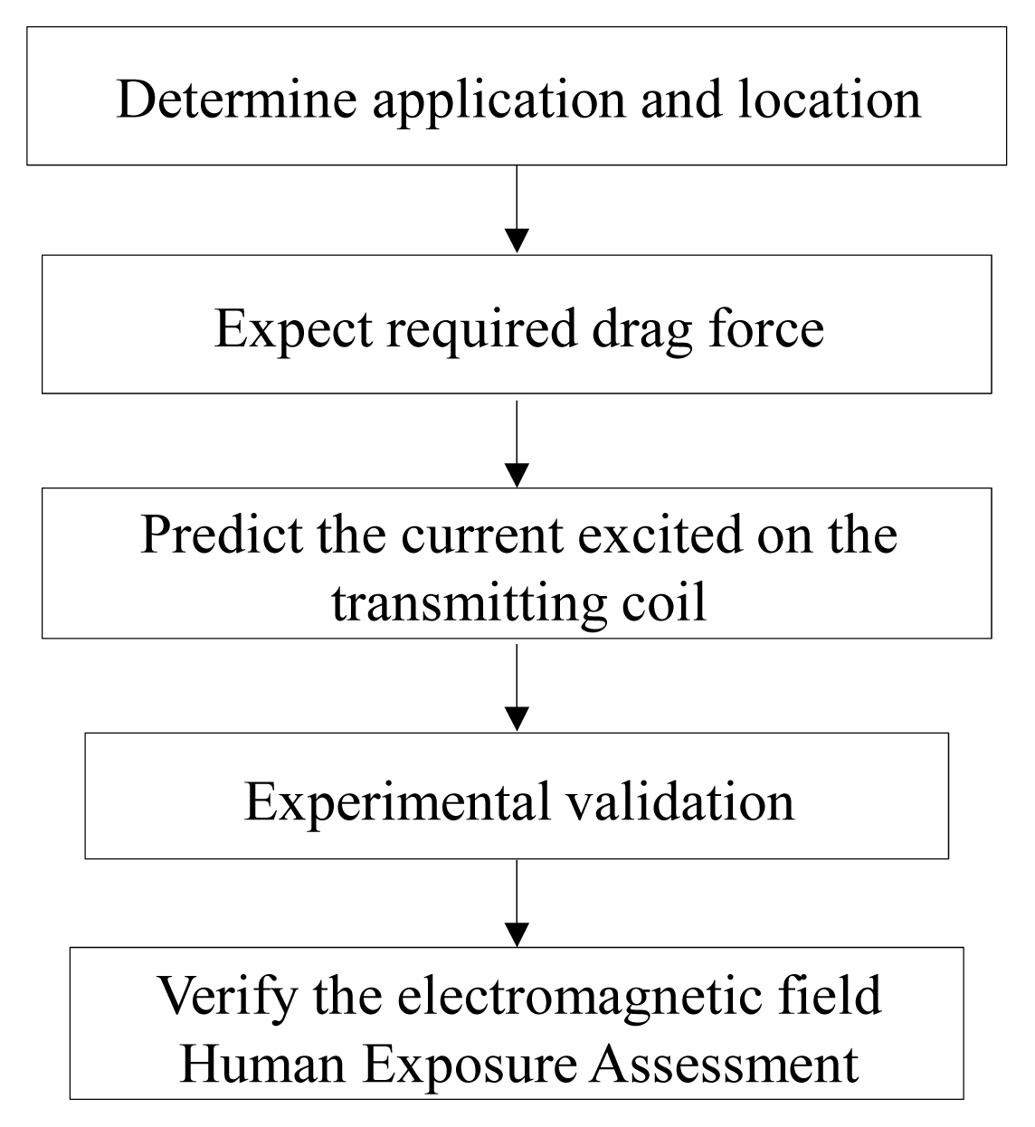
Accordingly, the design procedures for microrobot propulsion can be organized as shown in Fig. 1. Once the location and purpose of the microrobot are determined, it is possible to derive the required drag force, which allows it to move in a certain range of velocity. In this research, magnetic force can be used as an external force and was determined according to Eq. (3). The microrobot and designed system were then verified experimentally. Finally, an assessment of human exposure to the electromagnetic field level was conducted through a simulation.
III. Propulsion of Microrobot in a Tube
Predicting the required force on a microrobot is essential for designing the system. Many studies apply the drag force (FD) as in the following equation, which is applied to an external flow or free stream condition.
where Žü, v, CD, A are the density of the fluid, the velocity of the microrobot, the drag coefficient, and the cross-sectional area of the fluid, respectively.
Comparing the calculation and simulation results, they correspond to each other, achieving error rates lower than 4%. However, this equation can only be applied to the free stream condition. Since this research assumes that the size of the microrobot is comparable to that of the blood vessel, it is more reasonable to consider the internal flow condition. Because of unpredictable turbulence, calculating the exact equation of the drag force for an internal flow condition is difficult. Instead, the commercial finite element method (FEM) of analysis, Ansys computational fluid dynamics (Ansys CFD) can be used to obtain the propulsion force of a microrobot in tube conditions.
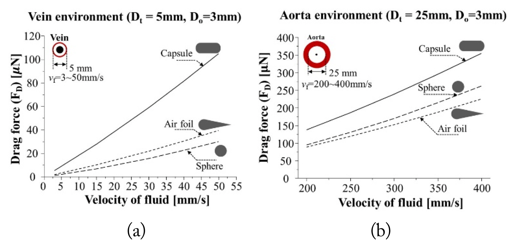
Fig. 2 shows the velocity of the fluid versus the drag force. The drag force on the graph indicates the force required to maintain its position against the stream when the fluid flows past the microrobot at a certain velocity. Considering that the fluid speed in a vein is 3ŌĆō50 mm/s, the required propulsion force for a microrobot is in the range of 2 ╬╝N to 100 ╬╝N. On the other hand, in the aorta, whose diameter is 25 mm, the required drag force is around 80 ╬╝N to 350 ╬╝N. These simulated results suggest that the order of the required propulsion force on the microrobot in the tube is in the a-╬╝N range.
In this research, we selected the specific velocity of blood vessels in the vein and aorta as 3 mm/s and 200 mm/s, respectively. Under these conditions, the force required to move against the blood flow is described in Fig. 2. As the blood velocity of the aorta is around 70 times higher than that of the vein, the required force on the aorta was evaluated at about 10 times higher than that of the vein. Moreover, as can be expected, the drag force will differ depending on the outer shape of the microrobot. This research considers a capsule shape since the shape of the microrobot is determined by a bar-shaped ferrite.
IV. Experimental Verification
To validate that the ╬╝N range of propulsion force or drag force is enough to allow the microrobot to move against gravity, experimental verification was conducted. In general, venous blood is hard to define, according to [2]. For this reason, in this research, we assumed the medium to be an eligible oil and not a vein condition.
1. Experiment Setup
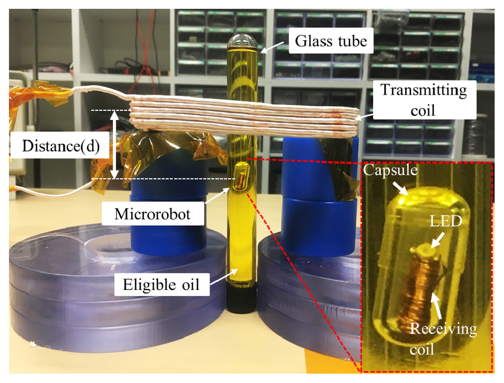
Fig. 3 shows the experimental setup, including a 25-turn transmitting coil and the fabricated microrobot. The receiving coil is wound along a ferrite sheet bar whose relative permeability is 150, and an LED is applied as an active circuit. The microrobot is sealed into a capsule-shaped hydrophilic material. To prevent it from dissolving, the glass tube is filled with oil.
As this research focuses on moving the microrobot upward against gravity, the tube is stood between two blocks. As it is not easy to create a balance between buoyancy and gravity, the experiment started when the microrobot was 5 cm away from the transmitting coil. Detailed electrical parameters and dimensional parameters are listed in Tables 1 and 2.
2. Derivation of Force Required to Move a Microrobot
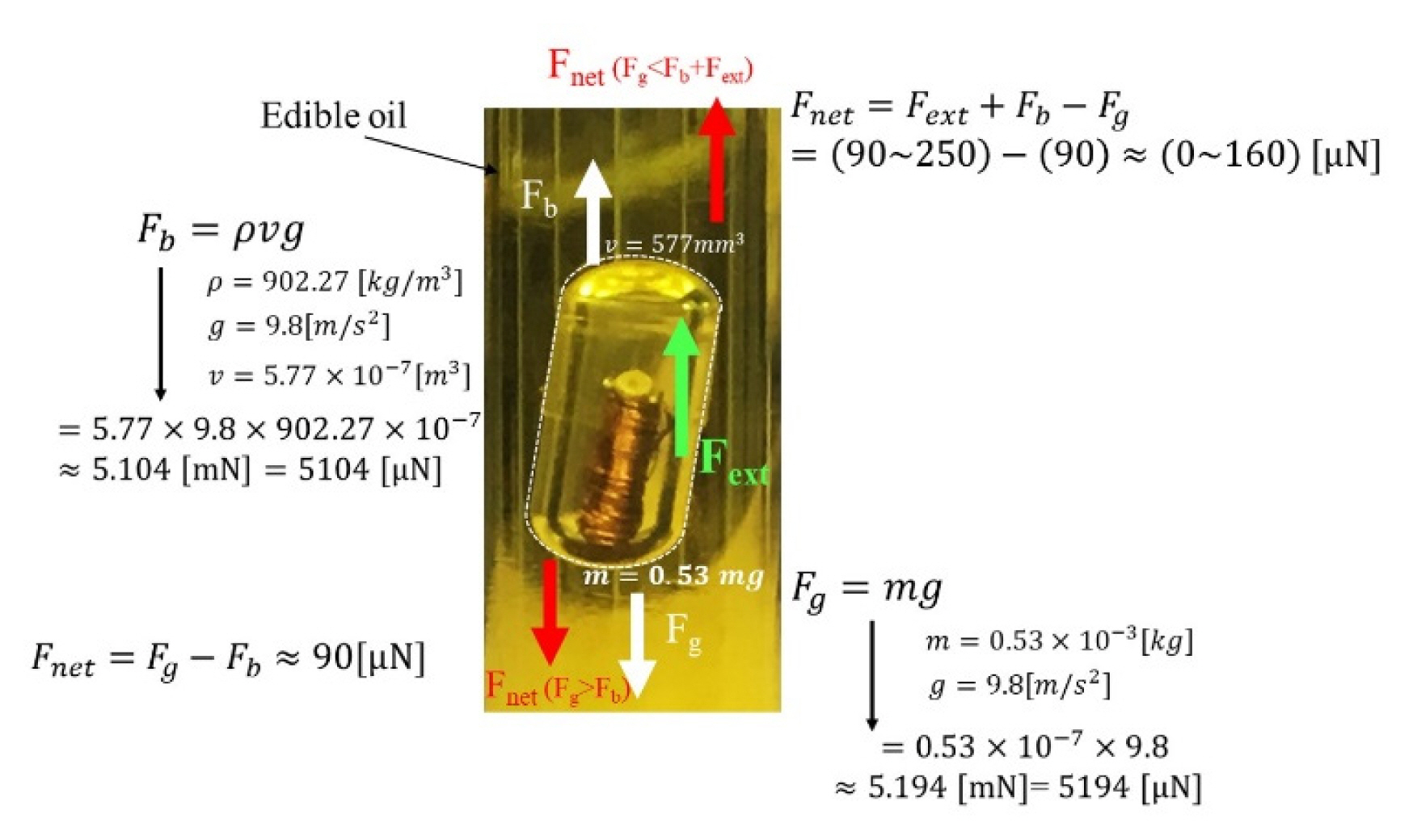
When the microrobot is inserted into the fluid, it is affected by both gravity and buoyancy, as illustrated in Fig. 4. Considering that the mass of the microrobot is 0.53 mg, the gravity on the microrobot can be determined to be 5.194 mN.
Meanwhile, considering that the density of the oil is 902.27 kg/m3 and the volume of the capsule is 577 mm3, the buoyance of the microrobot can be calculated as 5.104 mN, which is 90 ╬╝N lower than gravity. Thus, it will require more than 90 ╬╝N to move the microrobot upward.
According to Eq. (3), it turns out that a 23-A current on the transmitting coil is required to induce the current needed to generate 90 ╬╝N in the microrobot when the distance between the transmitting coil and the receiving coil is 5 cm. When the WPT system is turned off, the time varying magnetic field is not generated, and therefore, there is no external force. In this case, the microrobot slowly moves downward because the gravity is higher than the buoyancy. On the other hand, when the WPT system is activated, the time-varying magnetic field introduces a magnetic force on the microrobot, and this acts like an external force. Since the transmitting coil is located above the microrobot, the external force is applied upward in the transmitting coil direction.
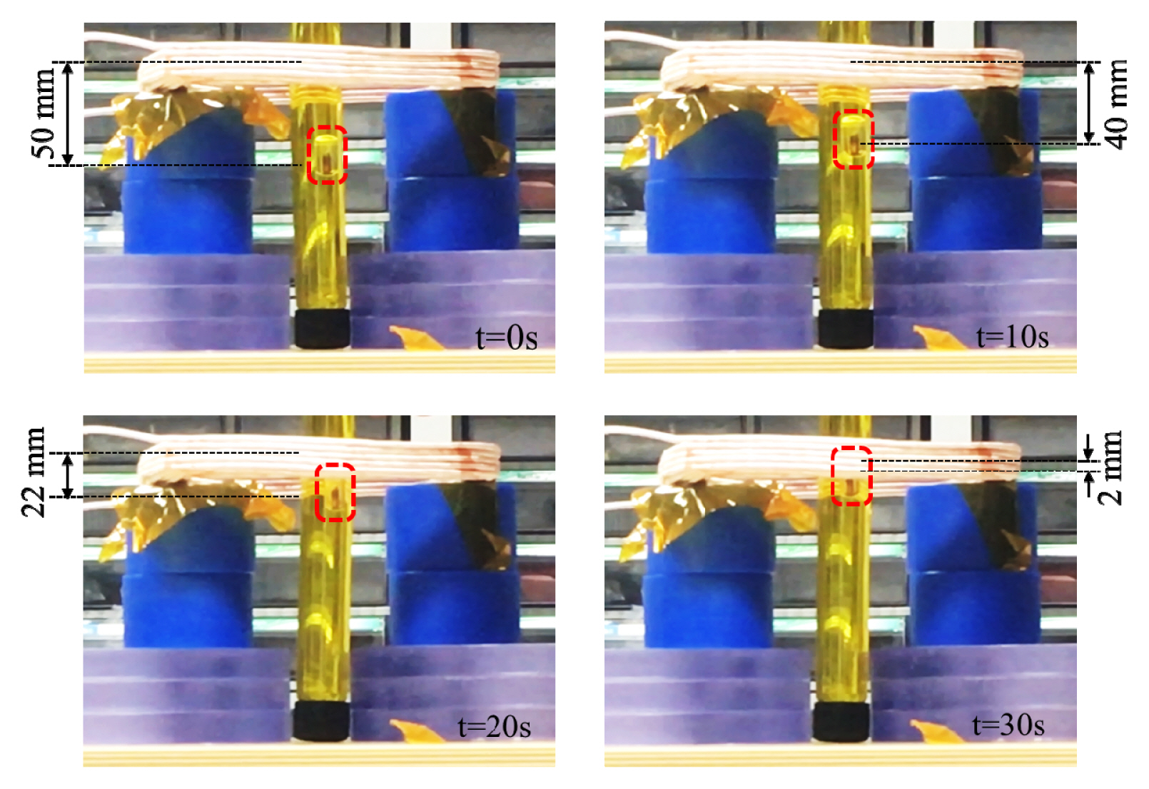
The movements of the microrobot when the WPT system was activated for 30 seconds were captured and are presented in Fig. 5. As time passed, the microrobot moved upward against gravity due to the applied external magnetic force. The time-average speed in 30 seconds was 1.67 mm/s.
Fig. 6 illustrates the applied external force depending on the position of the microrobot. These values were calculated using Eq. (3), since the current of the transmitting coil, the relative permeability of the ferrite sheet, and the vertical distance between the transmitting coil and the receiving coil are known values. Comparing the force and velocity as the microrobot moved closer to the transmitting coil shows that the propulsion force increased.
Accordingly, the moving velocity of the microrobot was observed to increase as the microrobot approached the transmitting coil. It turns out the time-average speed of the microrobot at 10-second intervals was 1.0 mm/s, 1.8 mm/s, and 2.0 mm/s. This implies that the microrobot is able to move upward against gravity, achieving a-mm/s range velocity in the fluid.
V. Electromagnetic Field Human Exposure Assessment
Although the proposed system was verified through experiments, before it can be used as an implantable microrobot, it is necessary to evaluate the level of human exposure to the applied electromagnetic field (EMF). For human exposure assessments, the commercial electromagnetic simulation software Sim4Life can be used. Since the microrobot is designed with an operating frequency of 100 kHz, a magneto-quasi-static (MQS) approximation solver is used. The MQS approximation assumes that the induced current in the human body does not interfere with the incident magnetic field, and this is valid for localized exposure from WPT systems below 10 MHz [22]. In addition, according to the International Commission on Non-ionizing Radiation Protection (ICNIRP) guidelines, both the internal electric field and synthetic aperture radar (SAR) should be considered at 100 kHz [23, 24].
To evaluate the internal electric field and SAR, an anatomical human body model, Duke (a 34-year-old male), taken from Information Technologies in Society (ITŌĆÖIS), was used [25]. The simulation setup for the EMF human exposure assessment is shown in Fig. 7. The transmitting coil was wrapped around the calf, and the receiving coil was placed in a vein. The vertical distance in the z-axis direction between the microrobot and the transmitting coil was 5 cm, which is the same as in the experiments, and the distance in the y-axis direction was 6.4 cm away from the outermost point of the transmitting coil.
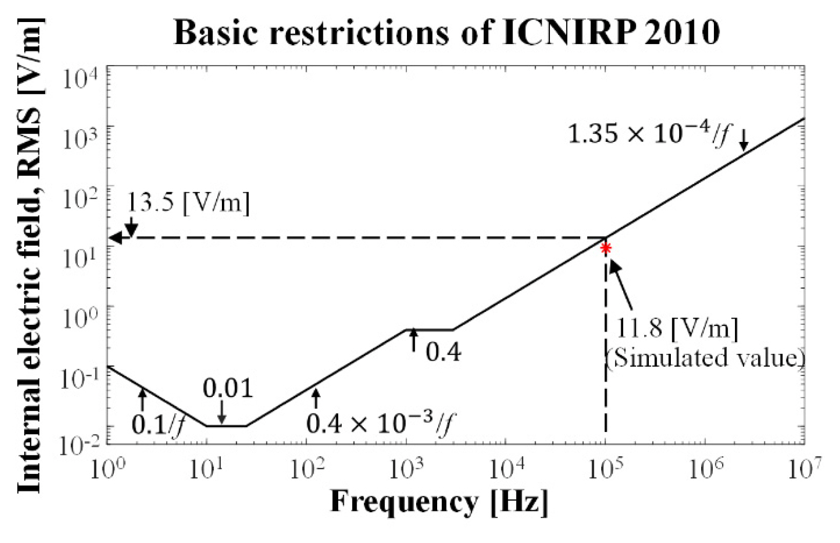
Fig. 8 shows the basic restrictions for the general public in terms of internal electric fields, and also shows the simulation result at 100 kHz. The simulated internal electric field was 11.8 V/m, which is less than the basic restriction of 13.5 V/m, so the designed microrobot complies with the guidelines. Fig. 9 shows the local SAR simulation results.
For the local SAR evaluation, the limits for the head/body or limbs are 2 W/kg and 4 W/kg, respectively, depending on the area exposed to the EMFs. In this simulation, the microrobot was located in the limb, and the simulation result was 0.5988 W/kg, which satisfies the limit of 4 W/kg. Therefore, it was confirmed that the proposed microrobot satisfies the ICNIRP guidelines based on the results of the human EMF exposure assessment through internal electric field strength.
VI. Conclusion
Microrobots have high potential value as implantable devices. To maximize their utility and minimize the size of the microrobot, a wireless power transfer-based microrobot propulsion system is introduced. Considering that the blood vessel is a kind of tube, the microrobot was inserted into a glass tube filled with fluid for experimental validation. Through experimentation, it was shown that a 3-mm microrobot can be moved against gravity, achieving an average velocity of 1.68 mm/s for 30 seconds. Moreover, a simulation was conducted to ensure that the human EMF exposure was within acceptable levels. The results showed that the proposed system satisfies the IC-NIRP guidelines, including the internal electric field strength and SAR evaluation.