I. Introduction
In the past, beamforming technology was mainly used in the satellite communication and radar fields. However, as the importance of commercial 5G technology and high-capacity datalink technology increases, the need for high-speed and long-distance communication is becoming essential [1–12].
Generally, beamforming technology can be classified into a passive and an active phased array antenna. The passive phased array antenna controls the phase using passive elements, such as a Butler or a Blass matrix. It has the advantage of fast and simple beam steering. However, a passive phased array antenna has the disadvantage of changing the beam’s direction according to the situation and recovering when antenna failure occurs [13–16]. The active phased array antenna forms a beam through a transmitter (Tx) or receiver (Rx) module capable of controlling the amplitude and phase for each radiating element or in units of sub-arrays. The active phased array antenna has the disadvantages of complexity and high-power consumption. However, it has the advantage of steering the beam direction with precision and forming multiple beams.
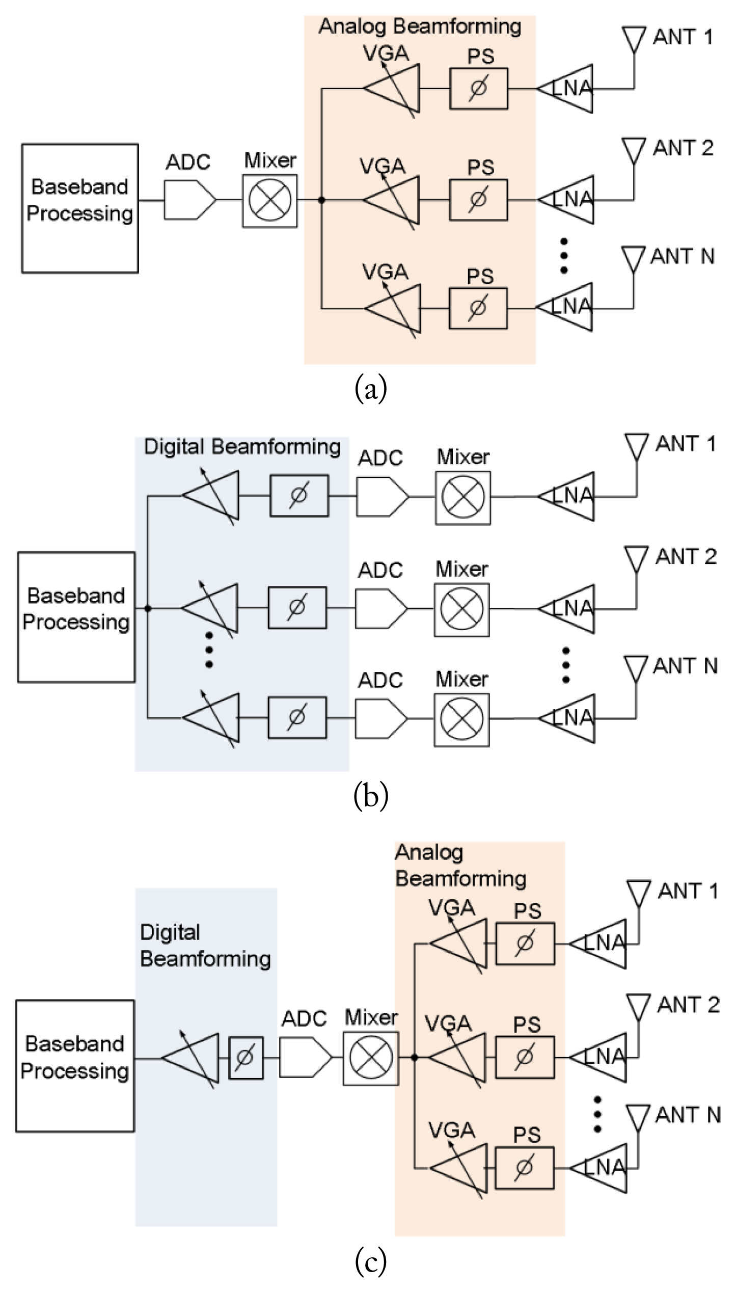
Active phased array antennas are classified into analog, digital, and hybrid beamforming methods according to their phase and amplitude controlling configuration. A comparison of Rx active phased array antenna beamforming system block diagrams is shown in Fig. 1.
In general, the analog beamforming method forms a beam through the phase and amplitude changes in the radio frequency (RF) path, as shown in Fig. 1(a). The analog beamforming has the advantage of a simple configuration and a small size. However, phase shifter (PS) precision and noise figure (NF) degradation due to the phased shifters and the variable gain amplifier are performance challenges for this technique [7, 17].
Digital beamforming controls phase and amplitude after digitizing the signal delivered to the analog to digital converter (ADC) through RF and analog paths, as shown in Fig. 1(b). Digital beamforming has the advantages of precise phase shifting and building multiple beams. However, digital beamforming requires many ADCs and has the disadvantage of increasing power consumption and production costs due to its signal processing. However, due to the recent development of digital technology, these shortcomings are being overcome.
Hybrid beamforming combines the advantages of both analog and digital beamforming. However, hybrid beamforming has the disadvantage of the complexity of implementing the beamforming unit which controlling both analog and digital. In addition, the performance of hybrid beamforming is sub-optimal compared to digital beamforming [18–22].
This study used a digital beamforming antenna because it has high steering accuracy, is compact and lightweight, and can be mounted on an aircraft for aerial relay communication. The proposed multi-beam antenna system has the advantage on compact integration from array antennas to digital beamforming and tracking units with high performance of beam pointing accuracy and gain-to-noise temperature (G/T). In addition, full azimuth beam steering is expected to be possible by utilizing a continuous array of presented antennas. Due to its tile structure, the desired antenna can be easily reconstructed on various platforms.
Section II describes the system considerations for Rx multi-beam phased array antennas and the design of each component. Section III describes the system implementation and the performance test results of the proposed Rx multi-beam phased array antenna.
II. Design of Rx Multi-Beam Phased Array Antenna System
1. Design Specification of Rx Multi-Beam Antenna System
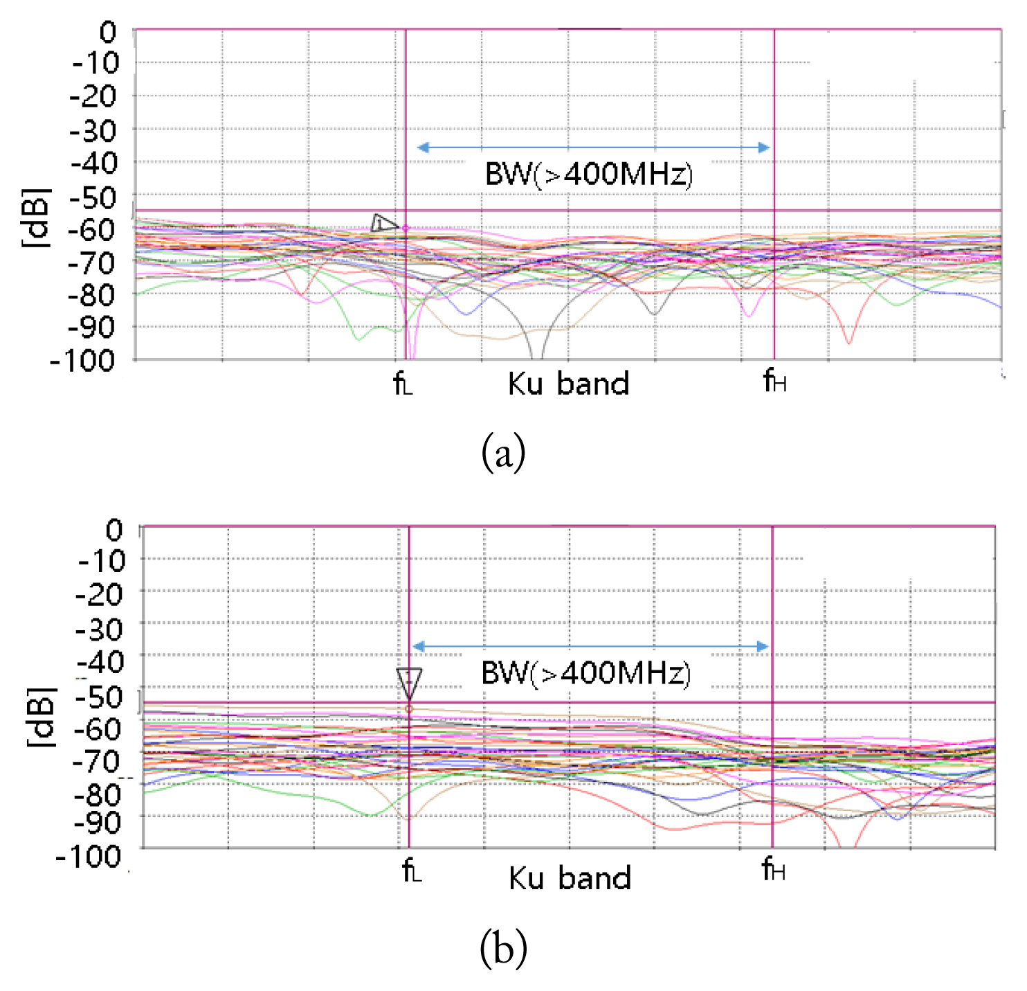
The presented Rx multi-beam antenna system considers distance coverage of about 50 km with full high definition (FHD) transmission. The Rx multi-beam antenna requires a G/T of −12 dB/K per beam to satisfy the link budget when the counterpart mission aircraft transmits with an equivalent isotropic radiated power (EIRP) of 19 dBW. Table 1 shows the design goals of the Rx multi-beam antenna. The designed multi-beam antenna occupies 40 MHz of the Ku band (about 15 GHz) as a receiving band. The multi-beam is a 4-channel signal (ch1, ch2, ch3, ch4) and consists of frequency division with a bandwidth of 10 MHz per channel. For the G/T, array antenna gains of 21 dBi and an NF of less than 5 dB are required. The beam steering angle coverage of the Rx antenna is from −18° to 18°, and a pointing accuracy of less than 1° is needed.
2. Design of Rx Array Antenna Unit
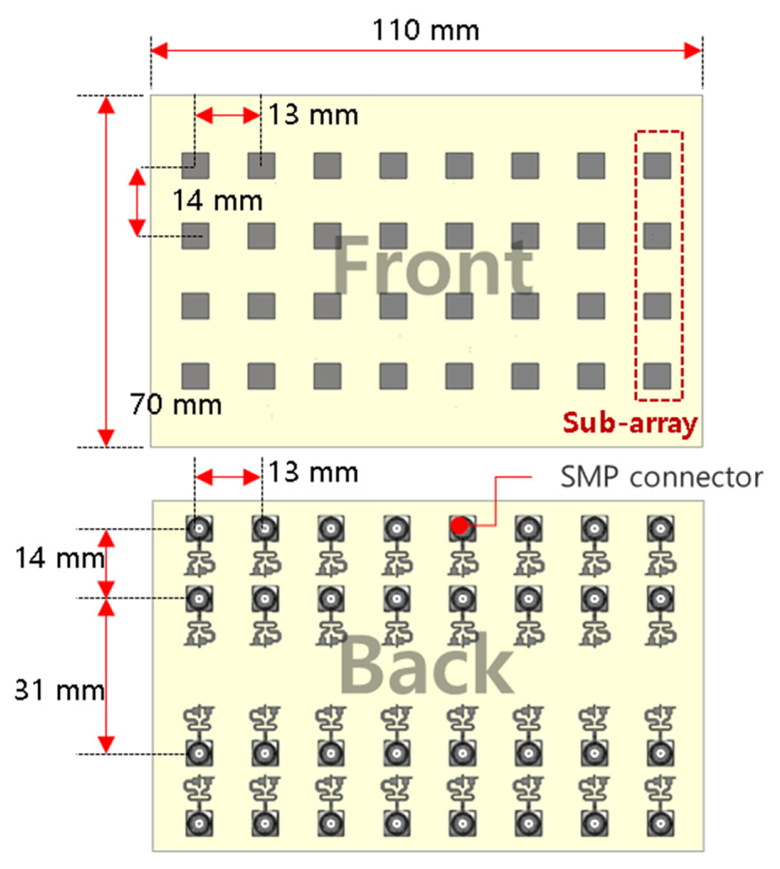
The design of the Rx array antenna is shown in Fig. 2. It is designed with a patch antenna structure to secure a wide frequency range in the Ku band through slot coupling feeding. It is designed to have dual feed structures to support circular polarization. The substrate with the micro-strip patch antenna is made of a low dielectric constant Teflon material (ɛr = 2.2, tanδ = 0.0009@10 GHz). A unit patch antenna has a gain of above 7 dBi, an axial ratio of 1.7 dB, and a beamwidth of about 78° horizontally and vertically in simulation.
The technical concept of aerial relay communications is considered in the designing of an array antenna. The antenna system is designed to be wide beamwidth in the elevation angle to minimize the change in the beam steering angle due to the mission aircraft’s altitude difference. In addition, it needs to be designed with narrow beamwidth in the azimuth direction to distinguish between mission aircraft in similar positions. A unit patch antenna is arranged 4 × 8 to meet the operation requirements of the array antenna. The simulated gain of the designed Rx array antenna is above 22 dBi, and the beamwidth is 9.5° in the horizontal direction and 18° in the vertical direction. Active S11 is designed so that the Rx antenna performance has a constant matching characteristic according to the beam steering angle. The simulated active S11 is shown as −4 dB and −10 dB in steering angles of 0° and 54°, respectively.
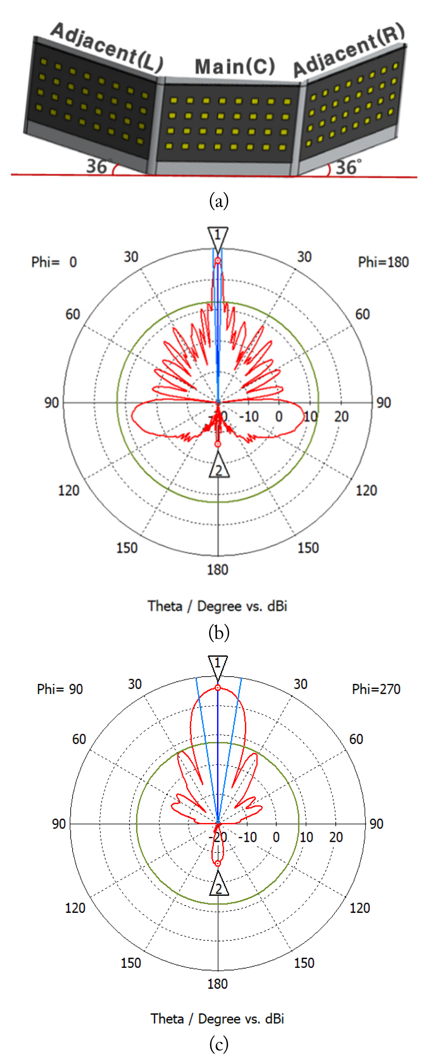
The proposed Rx multi-beam antenna is operated by interlocking one main and two adjacent tiles. The configuration of the adjoining tile antenna system is shown in Fig. 3(a). The adjacent tiles are arranged to be inclined 32° from the main tile. This is to design an Rx antenna capable of full azimuth beam steering through the additional arrangement of adjacent tiles. The antenna expanding from a 4 × 8 to a 4 × 32 antenna array can be obtained with about 1 dB loss due to its inclined tile configuration. This arrangement can improve antenna gain and beam pointing error. The array antenna’s gain confirmed by simulation is above 25 dBi, and the beamwidth is 3.5° in the horizontal direction and 18° in the vertical direction, as shown in Fig. 3(b) and 3(c).
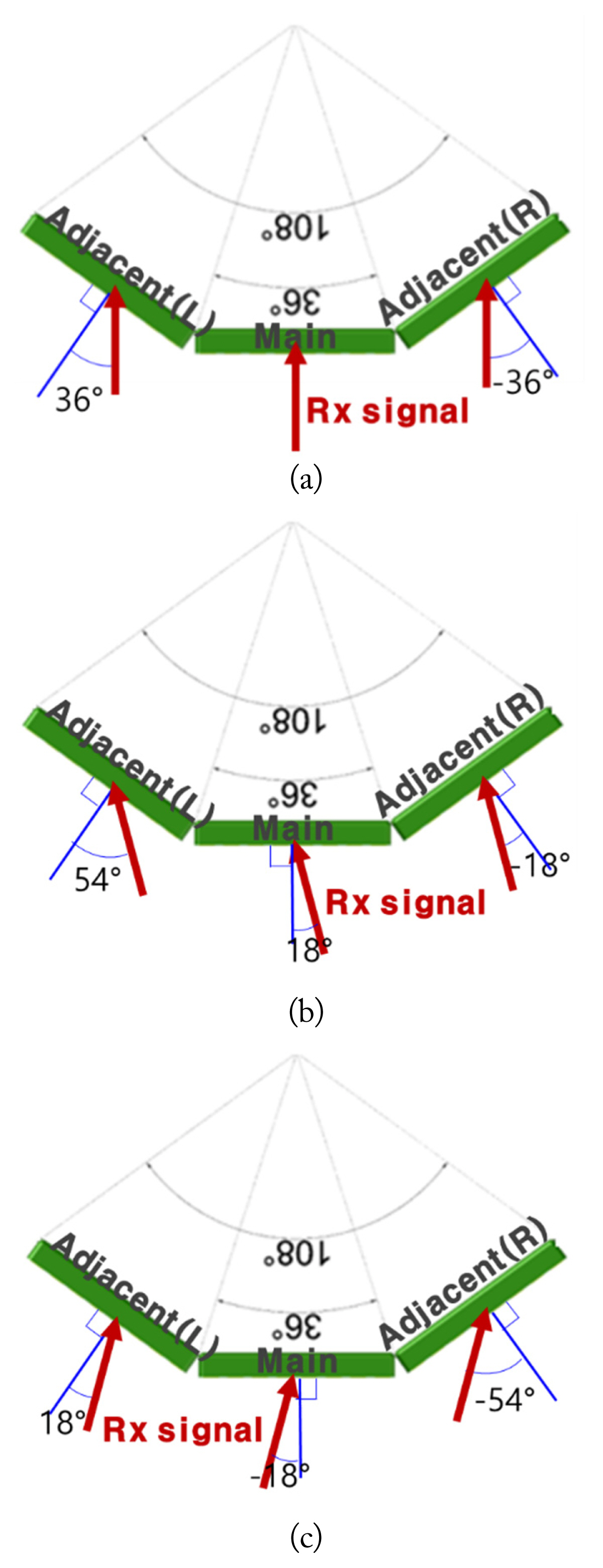
Fig. 4 shows the operation of three adjacent tiles in the Rx multi-beam antenna system. Because the adjacent tiles are inclined by 36°, the beam is steered ±36° from the adjacent tiles for boresight beam direction. The adjacent tiles direct the beam 54° and −18° in the adjacent (L) and adjacent (R) tile to form an 18° beam. The adjacent tile’s steering angle is determined through (1) and (2) according to the beam direction of the main tile for fast calculation.
3. Design of Tx-Rx Isolation Unit
In general, aerial common datalink communication operates with frequency division duplexing (FDD) in Tx and Rx antenna systems. It is necessary to integrate a duplexer to support FDD with a single antenna. However, it is hard to implement a duplexer in a compact chip in the Ku band due to its manufacturing limits. Therefore, the proposed multi-beam antenna system is designed for the Tx and Rx antennas using space separation, as shown in Fig. 5(a). Wide space separation can improve Tx-Rx isolation performance, but it should be compact when considering mounting on an aircraft. The high output power of the Tx antenna is coupled to the Rx antenna and can saturate the Rx antenna. Therefore, it is essential to design a Tx-Rx isolation unit with sufficient isolation in a compact size [23].
The unit power amplifier (PA) output power in the Tx antenna system is 20 dBm, and the maximum available input level of the low noise amplifier (LNA) is −35 dBm in the Rx antenna. Therefore, a Tx-Rx isolation unit with isolation performance of at least −55 dB is required.
Fig. 5 shows a designed Tx-Rx isolation unit for the Rx antenna system. It minimizes the nearfield signal transmitted from the Tx antenna to the Rx antenna by increasing its electrical length and forming a soft surface in the isolation unit. The isolation performance by EM simulation shows −60 dB for boresight and −56 dB for the 54° steering angle.
4. Design of RF Integration Unit
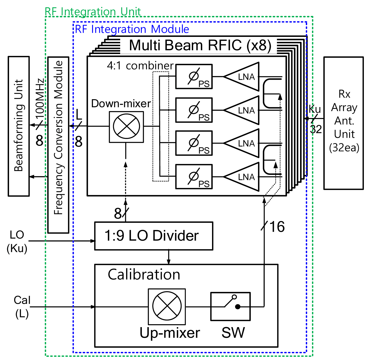
The Rx radio frequency integration (RFI) unit is composed of an RFI module and a frequency conversion (FC) module, as shown in Fig. 6. Because there are 32 patch antennas in one tile, 32 receiver RF paths are required. In this work, the RFI module consists of eight radio frequency integrated circuits (RFICs) to cover all Rx paths. Each RFIC consists of four LNAs, four PSs, a 4:1 signal combiner, and a frequency down-conversion mixer. Through RFIC, 32 Ku-band received signals are output as eight L-band signals. In LNA, the NF is designed to be less than 7 dB, including board and feeding loss.
The frequency down-conversion module receives eight L-band signals from RFICs and converts them into eight 100 MHz bands to deliver an ADC. In addition, to equalize the intensity of the received signal at the ADC, the module is designed to perform automatic gain control (AGC) using a variable gain amplifier (VGA) and a variable attenuator. The FC module is designed to be adjusted in 0.5 dB steps with a maximum 50 dB gain and a minimum 15 dB gain.
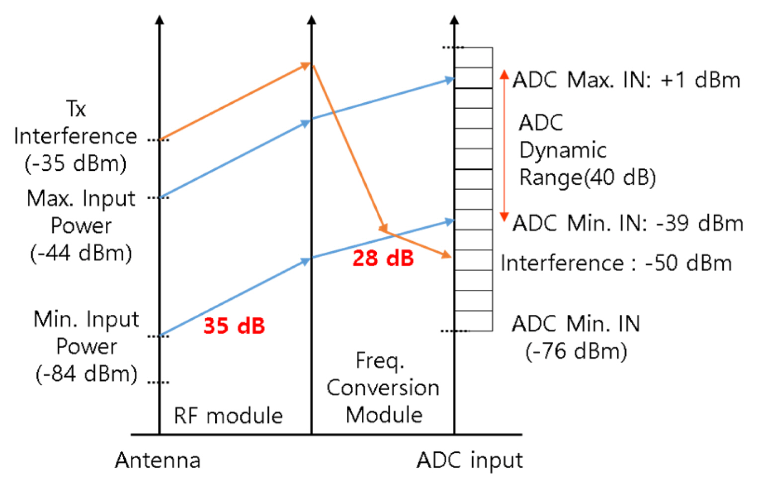
When considering the operating concept of a multi-beam antenna for the aerial relay, there may be a mission plane in which a communication distance difference occurs in the same beam steering angle. The difference in the multi-beam received signal is mostly generated due to the distance from the mission planes. All received signals are valid ones, which include communication data. Therefore, in this receiving antenna system, the ADC’s receiving dynamic range is designed to be 40 dB so that 100 times the difference in receiving signal power can be restored. The antenna system’s minimum received input power is −84 dBm, and the maximum received power level excluding the Tx coupling signal, −35 dBm, is −44 dBm. Fig. 7 shows the Rx path power budget of the RFI unit considering the multi-beam reception dynamic range of 40 dB.
In designing an active phased array antenna, the calibration process is essential to minimize the beam steering error and optimize the beam pattern. The Rx internal calibration signal can apply to the LNA input path for the calibration process using a signal coupler. The phase and amplitude error of the receiving path can be found. Two calibration signals are used for each RFIC after 16 branches by switching the signal for calibration. The Rx calibration signal is converted into L-band and converted to 100 MHz through the RFI unit. The signal is then transmitted to the digital beamforming unit through an independent ADC for calibration. The digital beamforming unit checks the phase and amplitude of the signal for each Rx path, calculates the error, adjusts phase of the PS in the RFIC, and gains of each path to make uniform in all Rx.
5. Design of Beamforming Unit
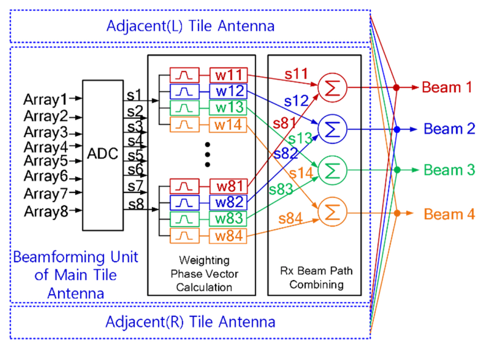
Fig. 8 shows the block diagram of the Rx multiple beamforming unit. Because each of the eight input signals contains all four channel signals, it is necessary to separate each channel after digital conversion. The digitally converted signal is branched into four signals, and a separated signal with minimized adjacent channel interference is obtained with a digital filter designed with a 10-MHz bandwidth. The phase weighting vector of the desired steering angle is multiplied for the separated signals for each channel. The Rx array antenna’s beam steering angle is obtained with high speed and precision using the phase comparison mono-pulse algorithm [24, 25]. Eight signals for each channel are synthesized into four multi-beams which the phase weighting vector for each channel is applied. The signal of the adjacent tile obtains a multi-beam signal in the same way. The multi-beam signals are then synthesized in the multi-beam interlocking unit.
III. Manufacture and Test Results of Rx Multi-Beam Antenna
1. Manufacture of Multi-Beam Antenna
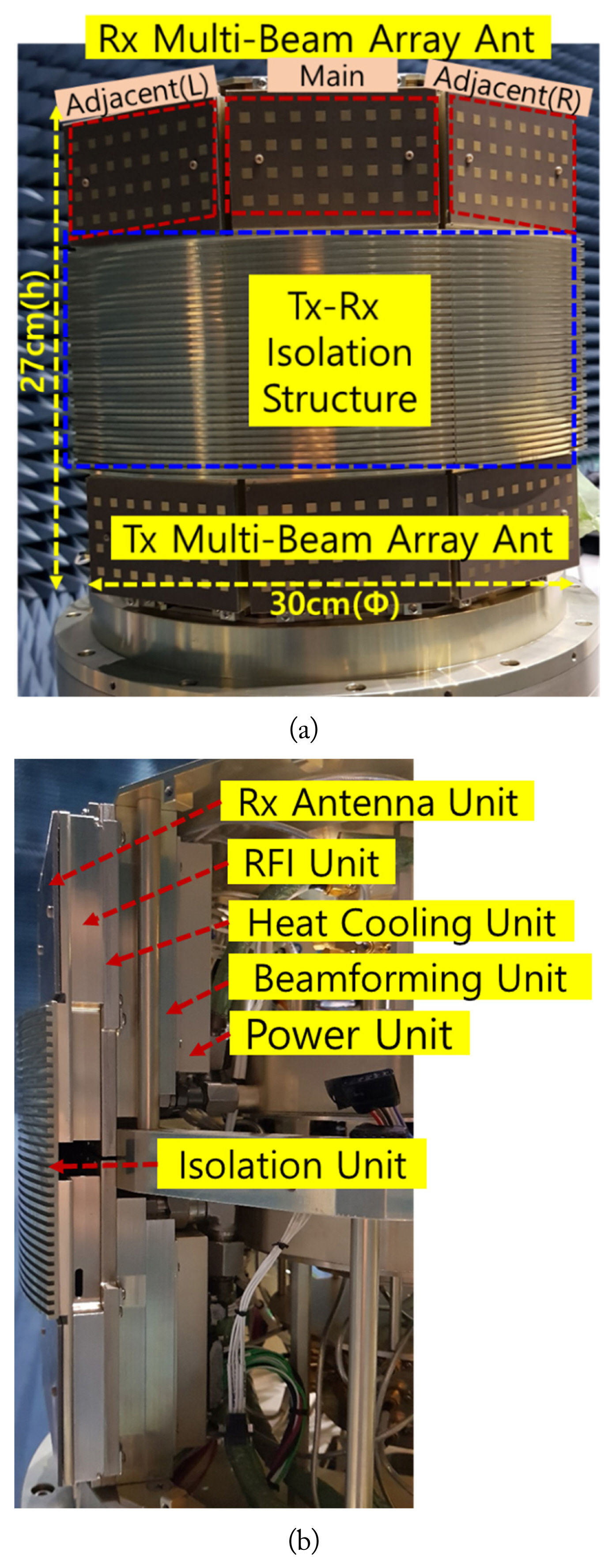
Fig. 9 shows the manufactured tile type multi-beam Rx phased array antenna. The proposed receiving antenna is designed in a tile with module housing instead of a tile with board-stacked in consideration of the military operating environment’s influence (altitude, temperature, and humidity). Because the Rx antenna consumes less power than the Tx antenna, performance degradation due to heat is not significant. However, to maintain a constant temperature in consideration of high- and low-temperature environmental conditions, a water-cooling heat dissipation structure is applied. The multi-beam antenna, including all Rx, Tx, and isolation structures, is presented in compact size with a height and radius of about 27 cm and 30 cm, respectively. Because the multi-beam antenna is inclined by 36° between tiles, it is possible to cover 360° in full azimuth by adding seven antenna tiles.
2. Test Configuration of Rx Multi-Beam Antenna
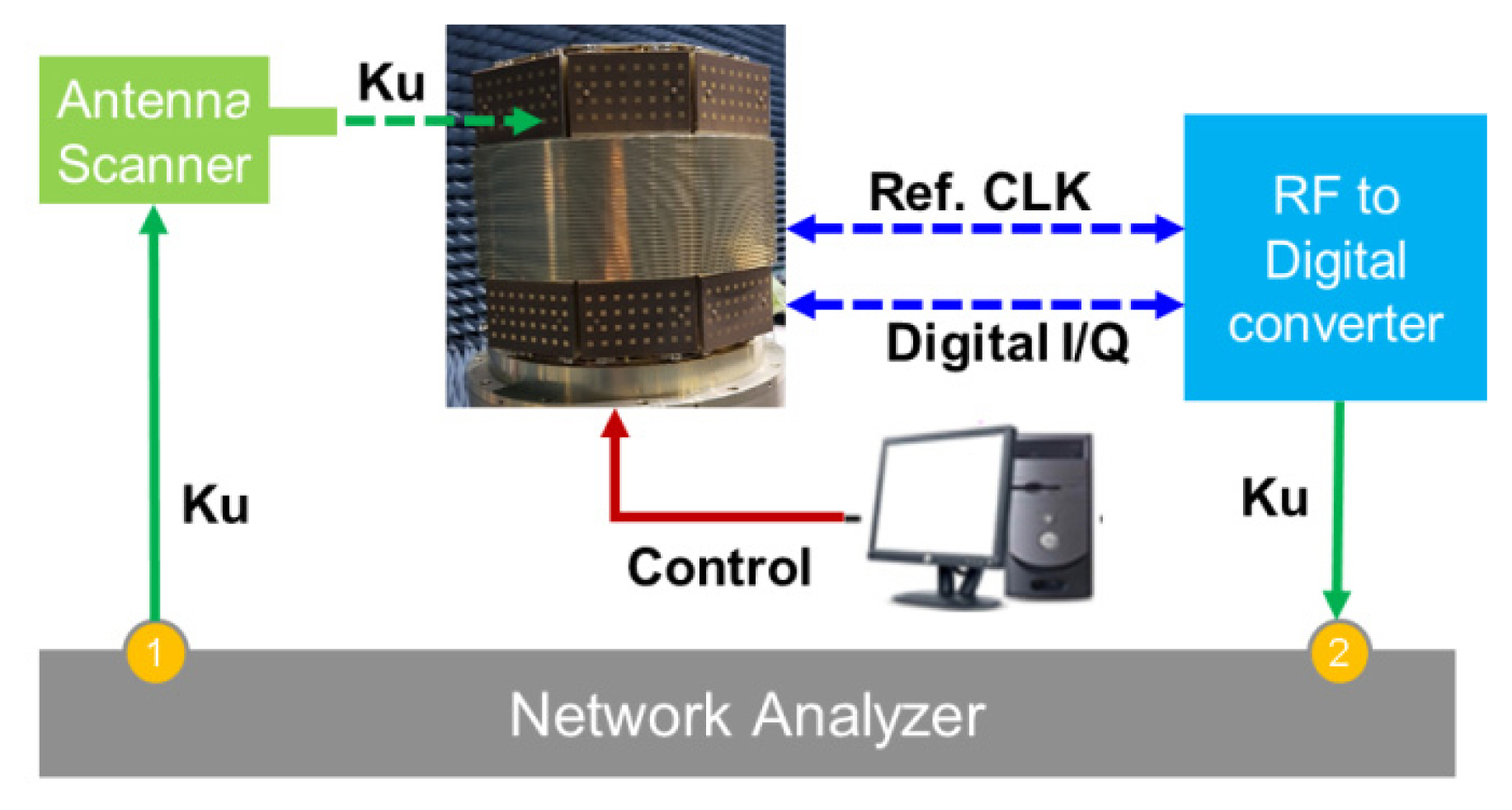
A Ku-band antenna scanner, a network analyzer, and a control unit are required for the performance test of the presented Rx multi-beam phased array antenna. The proposed multi-beam antenna receives a Ku band signal and outputs a digital I/Q. Thus, a module that converts digital I/Q input to Ku band is configured to test with a network analyzer. A positioner and scanner capable of measuring a nearfield of more than four times the scanning area of an Rx antenna are used to test the antenna pattern accurately. Keysight E8363B and E8257D are used as the signal analyzer and generator. The measurement configuration is shown in Fig. 10.
The beam steering test confirmed the beam formation with four beam angles of −18°, −9°, 9°, and 18°. This means that four independent beams can be formed from −18° to 18° and meet the Rx antenna requirement.
The maximum pointing error is less than 0.4°. The test results are summarized in Table 2.
3. Performance Test Results of Rx Multi-Beam Antenna
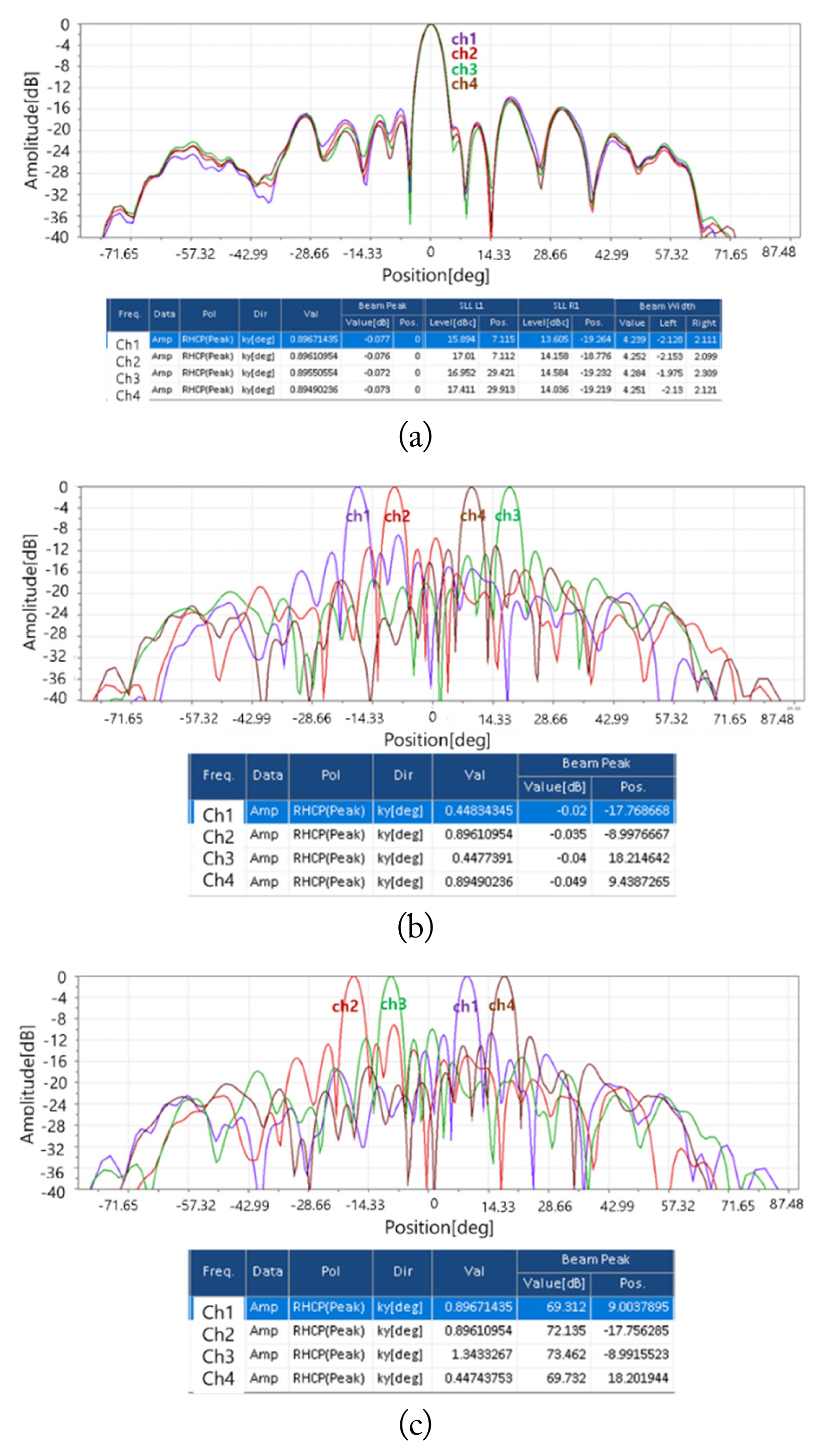
The beam pointing accuracy and G/T are tested as the main performance indicators of the Rx multi-beam antenna system. All tests are performed after calibration of the multi-beam antenna. If more precise calibration is completed, the test results’ sidelobe level and beam pointing accuracy can be further improved. First, the beam pointing accuracy test is performed by applying independent beam angles to confirm the simultaneous formation of four independent multi-beams and the precision of beam steering. The test results are shown in Fig. 11.
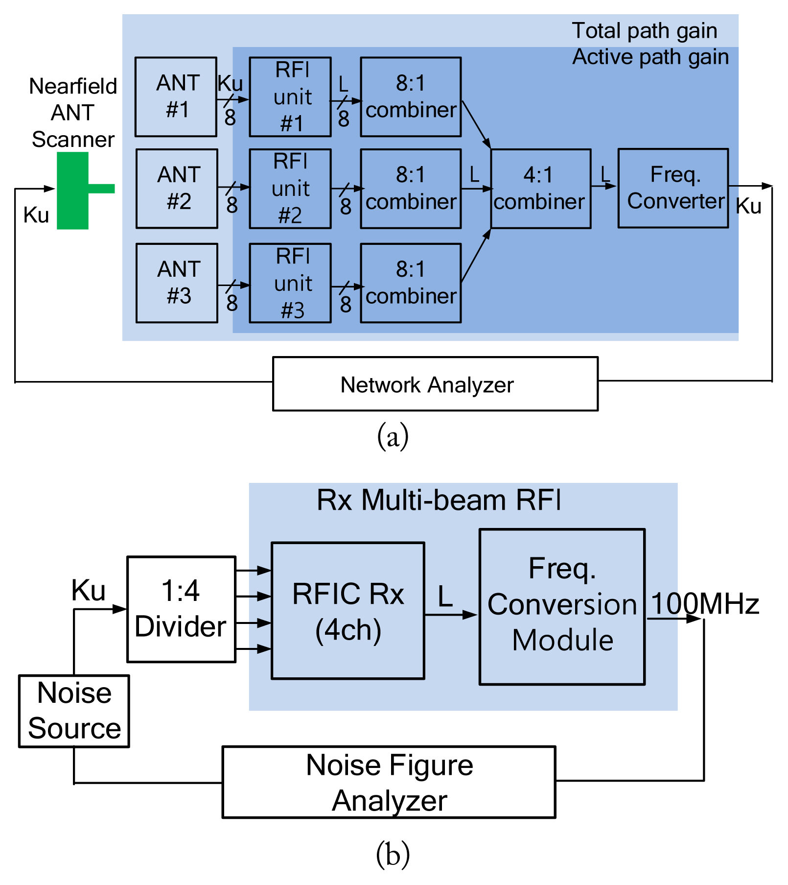
Regarding the boresight, the beam pointing error is below 0.1°. The beam width and 1st sidelobe level shows below 4.5° and −15 dB for left and −13 dB for right sidelobe, respectively. The beam steering test confirms that beam formation with four beam angles of ±18° and ±9° is possible. This means that four independent beams can be formed from −18° to 18° and that they meet the Rx antenna requirement. The maximum pointing error is less than 0.4°. The test results are summarized in Table 2. Because it is difficult to measure G/T directly, it is calculated using (3) for each beam of the multi-beam antenna system. The main and adjacent tiles of the multi-beam antenna are interlocked, and the antenna gain is evaluated using a nearfield measurement method. For an accurate antenna gain test, the total tile antenna path gain is measured including the RFIC of the RFI unit. The gain of the RFI unit is then measured without the antenna unit and is excluded from the total to consider any mismatch and feeding loss between the antenna and the RFI unit. For the Rx NF test, four sub-array antennas are combined to measure NF precisely in a single tile. Fig. 12 shows the block diagram of each test setup for G/T.
Table 3 summarizes the test results of G/T performance for Rx multi-beam antenna system. It shows above that there are −6 dB/K of G/T in each multi-beam, which satisfies the design specification of −12 dB/K. This means that the proposed Rx multi-beam antenna can cover about 50 km with FHD transmission.
IV. Conclusion
In this paper, we proposed an Rx multi-beam antenna system which available four independent beams for long distance communication in aerial. The multi-beams can be formed from −18° to 18° with a beam steering error of less than 0.4°. In addition, each multi-beam antenna has above −6 dB/K of G/T, which satisfies long distance aerial communication requirements. The proposed Rx multi-beam antenna has a compact size and can be mounted on an aircraft. To the best of our knowledge, the proposed multi-beam antenna is first implemented with high performance of its G/T and steering accuracy in compact size.