Compact Tri-band Bandpass Filter Based on Asymmetric Step Impedance Resonators for WiMAX and RFID Systems
Article information
Abstract
In this article, a simple method is developed to design a highly miniaturized tri-band bandpass filter (BPF) utilizing two asymmetric coupled resonators with one step discontinuity and one uniform impedance resonator (UIR) for worldwide interoperability for microwave access (WiMAX) and radio frequency identification (RFID) applications. The first and second passbands located at 3.7 GHz and 6.6 GHz are achieved through two asymmetric coupled step impedance resonators (SIRs), while the third passband, centered at 9 GHz, is achieved using a half-wavelength UIR, respectively. The fundamental frequencies of this BPF are implemented by tuning the physical length ratio (α) and impedance ratio (R) of the asymmetric SIRs. The proposed filter is designed and fabricated with a circuit dimension of 13.69 mm × 25 mm (0.02 λg × 0.03 λg), where λg represents the guided wavelength at the first passband. The experimental and measured results are provided with good matching.
I. Introduction
The field of microwave and radio frequency communication continuously demands a compact wireless transceiver for commercial products, especially in the combination of IEEE 802.11b/g (GSM), IEEE 802.11a wireless local area network (WLAN), global position system (GPS), radio frequency identification (RFID), and automotive radar system. One of the key components in such a system is a bandpass filter (BPF) with a compact size and high isolation, and its performance dominates the entire microwave communication system. For this, the design of a triple-band BPF with a compact size and low insertion loss plays an important role in the wireless transceiver, but this is a great challenge for circuit designers [1–6].
In the past several years, triple-band BPFs have been intensively proposed and investigated by combining two or more single BPFs, a stub loaded resonator (SLR), a step impedance resonator (SIR) with one or more step discontinuities, and multimode resonators (MMRs). The SIR with one-step discontinuity has more design freedom to control the spurious bands when compared to the traditional SIR, which has two step discontinuities, leading to more losses and a larger circuit size. It has the advantages of designing higher-order compact BPFs with a high selectivity and low insertion losses, such as dual-, tri-, quad-, or quintuple BPFs, because of its inherently higher order resonant modes [7]. A tri-band BPF loaded with a pi-section SIR was presented in [8] for GPS (Link-2), WiMAX, and WLAN applications, with the merit of a greater bandwidth but also with issues related to filter selectivity, insertion losses, and a larger size. In [9], another triple-band response was achieved using asymmetric SLRs for wireless medical telemetry service (WMTS), WLAN, and WiMAX applications, with the shortcomings of a high insertion loss, low fractional bandwidth (FBW), poor selectivity and larger circuit dimensions. To improve the isolation between the passbands as well as the passband insertion losses, a high-frequency selectivity triple-band BPF was designed and fabricated with Rogers RO-4003 material in [10] using a novel MMR for WCDMA/WiMAX/WLAN wireless applications. The filter had the strong merits of a greater bandwidth and low insertion loss, but the size of the filter still needs to be improved, and the circuit complexity also increases using MMRs. In [11], the authors utilized a double mode to design a filter giving three passbands for GSM and GPS wireless applications. The filter showed a good performance for insertion loss as well as high-frequency selectivity via exciting six transmission zeros (TZs) between the bands, but a larger circuit size was still considered a major drawback associated with the design. Another three-working band filter was designed using a composite-right/left-handed (CRLH) resonator in [12]. The presented filter had serious issues regarding FBW, circuit size, poor isolation between the passbands as well as insertion losses, especially for the first and third passbands, which were greater than 3 dB. To overcome this size problem and make the filter suitable for compact wireless transceivers, in [13], a high-selectivity dual-and tri-band filter was designed and implemented on Roger’s substrate material using a common resonator feeding technique. However, while the presented filter had good passband insertion loss, it also had lower FBW, and its size could still be upgraded. In [14], an asymmetric T-shaped SLR-based tri-passband filter was designed for 2.48/3.58/4.48 GHz wireless applications, resulting in wider FBW and low in-band insertion loss; however, the larger circuit area and poor isolation between the passbands were its major disadvantages. The authors of [15, 16] designed a triple-band BPF using SIR structure with good passband selectivity, but larger circuit dimensions were a major drawback associated with the design. Moreover, the later study had poor insertion loss as well as low FBW. Recently a uniform impedance resonator (UIR)-based tri-band filter was designed and implemented in [17]. The proposed design included a larger circuit area, poor FBW, and insertion losses. To improve the passband insertion loss, a compact three-passband filter was designed using ring MMRs in [18]. The proposed filter had good selectivity, but, again, the larger circuit area was still an issue.
In this article, an ultra-compact triple-band BPF is proposed that uses two asymmetric coupled resonators with one step discontinuity and one UIR for IEEE 802.16 (WiMAX) and RFID wireless applications at 3.7 GHz, 6.6 GHz, and 9 GHz with a FBW 7.52%, 5.1%, and 4.44%, respectively. The first and second passbands are achieved through asymmetric coupled SIRs, while the third passband are obtained using a half-wavelength UIR. The resonance frequencies of this BPF are determined by tuning the physical length ratio (α) and impedance ratio (R) of the asymmetric SIRs. Additionally, the coupling coefficient can be determined based on the space between the two resonator and the coupling gap between the pair of asymmetric SIRs and the 50-Ω input/output ports. The proposed triple-band BPF is then fabricated on a Rogers substrate, with the experimental results matching well with the measured results. Overall, this article presents a simple method for designing an ultra-compact triple-passband filter without a complex design and fabrication process.
II. Design Procedure of the Asymmetric SIRs
The basic structure of an asymmetric SIR is illustrated in Fig. 1, while the proposed filter topology along with the geometrical dimensions in millimeters (mm) is depicted in Fig. 2, where it is shown that it is fabricated on Rogers RO-4350 substrate with a thickness of 0.762 mm. The proposed asymmetric SIR topology consists of a high-impedance section (Z1) cascaded with a low-impedance section (Z2) which are bent in a ring-like shape to reduce the circuit size. A pair of 50-Ω coupling ports are attached to the asymmetric SIR at the input/output port to obtain the desired coupling coefficients. The proposed configuration has a one-step discontinuity when compared to the conventional SIR, which has a two-step discontinuity; due to this arrangement, the harmonics of the fundamental resonance frequencies can be easily shifted far away without increasing the circuit size or number of the discontinued step impedance sections. The length and width of the high and low-impedance sections are denoted by L1, W1, and L2, W2 with characteristic impedances Z1 and Z2, respectively, whereas θ1 and θ2 represent the electrical lengths of the high-impedance and low-impedance sections of the microstrip line, as shown in Fig. 1. The physical length ratio (α) and impedance ratio (K) of the asymmetric SIR can be defined as follows [7]:
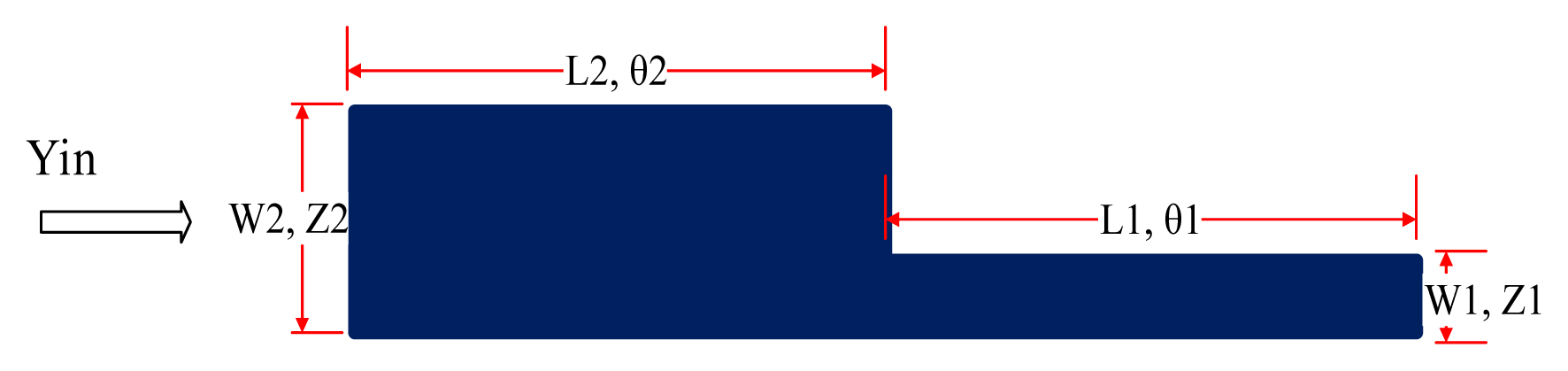
Proposed asymmetric SIR configuration with one step discontinuity.
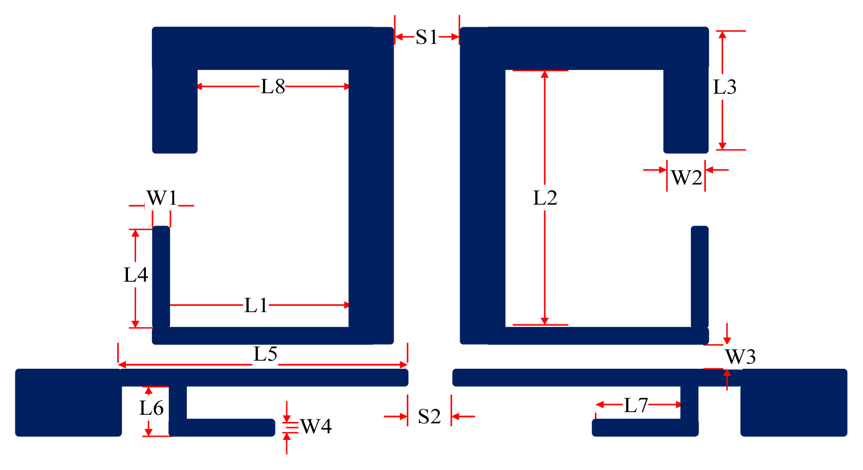
Proposed topology of the tri-band filter with geometrical dimensions in millimeters (L1 = 6.8, L2 = 11, L3 = 3.7, L4 = 5, L5 = 10, L6 = 1, L7 = 4.5, L8 = 6, W1 = 0.23, W2 = 1.4, W3 = 0.25, W4 = 0.8, S1 = 0.7, S2 = 0.2).
where θt is the total wavelength of the asymmetric SIR
where θ1 = β1l1 and θ2 = β2l2.
The characteristic input admittance, Yin, of the asymmetric SIR seen from the open-end can be found by neglecting the effect of the discontinuities, as follows:
The resonance condition occurs when equating the above equation to zero—i.e., Yin= 0. Thus, the proposed filter applications, such as WIMAX and RFID, are achieved simultaneously by choosing the appropriate impedance ratio (R = 0.45) and physical length ratio (α = 0.71), respectively.
III. Experimental Results and Discussion
An ultra-compact tri-passband filter with dimensions of 13.69 mm × 25 mm (0.02 λg × 0.03 λg) and 0.0006 λ2g circuit size, where λg represents the guided wavelength at the first passband, consisting of two asymmetric SIRs and one UIR fabricated on Rogers RO-4350 substrate with a relative permittivity of 3.66 and tested on an Agilent E5071C network analyzer is presented in this study. The first and second passbands centered at 3.7 GHz and 6.6 GHz were obtained by two coupled asymmetric SIRs for WiMAX and RFID applications, while the third passband centered at 9 GHz was achieved through the UIR, which is attached to the input/output port transmission line. The two asymmetric SIRs are designed in such a manner that they produce the desired coupling coefficient and quality factor with the input/output port of the microstrip line. Thus, the coupling coefficient and quality factor shown in Figs. 3 and 4 can be determined by the space, S1, between the two resonators, which is fixed at 0.2 mm, and the coupling gap, W3, between the pair of asymmetric SIRs and the input/output ports. The quality factor coefficient (Q) and coupling coefficient (Ke) can be found using the following expression [19]:
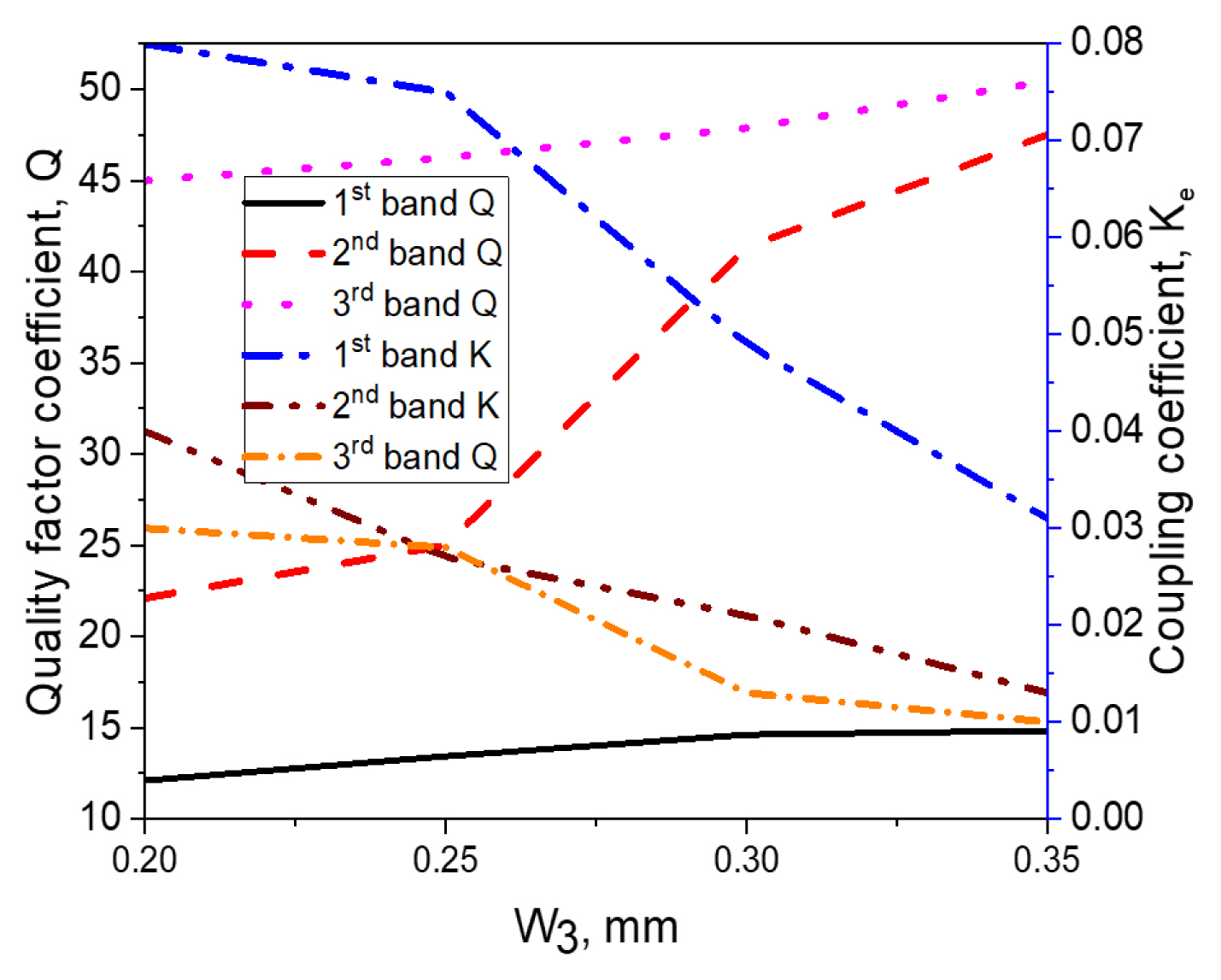
Plots of Q and K with W3 gap.
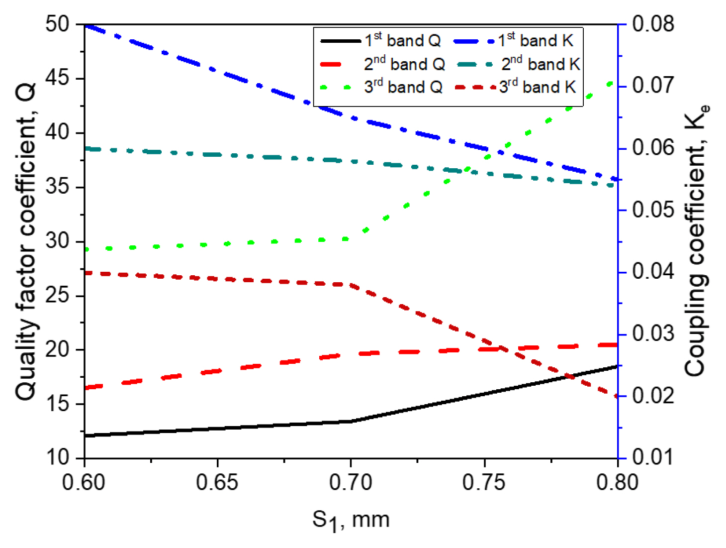
Plots of Q and K with S1 gap.
In the above equation, f1 and f2 demonstrate the lower and upper resonance frequency modes of the asymmetric SIRs, fc represents the resonant mode frequency, and FBW denotes the FBW (in a percentage).
In this paper, the first two passbands were generated using asymmetric coupled SIRs by choosing design parameters of a high impedance section (Z1 = 123.5 Ω, θ1 = 81.2°) with a strip width of 0.23 mm and a low impedance section (Z2 = 55.8 Ω, θ2 = 195.3°) with a strip width of 1.4 mm, respectively. The resonant frequency ratio (f2/f1 = 1.83, f3/f1 = 2.5) and the impedance ratio (R = 0.45) with a physical length ratio of α = 0.71 were selected for the proposed asymmetric resonator to generate the two passbands at the frequencies of 3.7 GHz and 6.6 GHz, respectively. The third passband was obtained through UIR centered at 9 GHz. Fig. 5 shows the filter response with and without the UIR, revealing that the third passband is obtained by the UIR. Fig. 6 demonstrates the simulated and measured frequency response along with a fabricated photograph of the proposed tri-band filter. This shows that the fabricated filter resonates at f1 = 3.7 GHz, f2 = 6.6 GHz, and f3 = 9 GHz for WiMAX and RFID wireless applications, with a 3-dB FBW of FBW1 = 7.52% for the first passband, FBW2 = 5.1% for the second passband, and FBW3 = 4.44% for the third passband, respectively. The minimum insertion loss (−20 log|S21|) is 0.99 dB for 3.7 GHz, 1.17 dB for 6.6 GHz, and 1.50 dB for 9 GHz, while the return loss (−20 log|S11|) is greater than 10 dB for the three passbands. The coupling between the two resonators (denoted by S1) and the gap, W3, between the pair of asymmetric SIRs and the input/output ports generate four TZs at 3.19 GHz, 4.71 GHz, 7.72 GHz, and 9.91 GHz between the passbands, thus obtaining a high selectivity. Moreover, the space, S1, should be minimal for achieving a lower insertion loss. Table 1 summarizes the comparison of the proposed triple-band BPF with other state-of-the-art filters in the literature, proving that the presented filter has a low insertion loss, wide bandwidth, and compact size as well as the potential to be utilized in WiMAX, RFID, and other tri-band applications [10–18, 20–22].
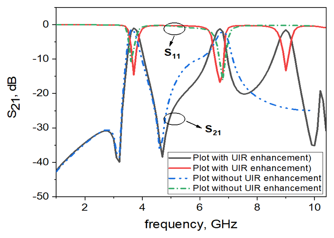
Frequency plots of the filter with and without a uniform impedance resonator (UIR).
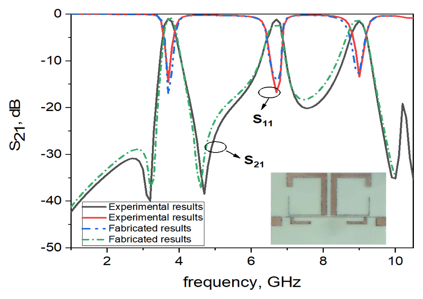
Experimental and fabricated resonance frequency plots of the asymmetric tri-band filter.
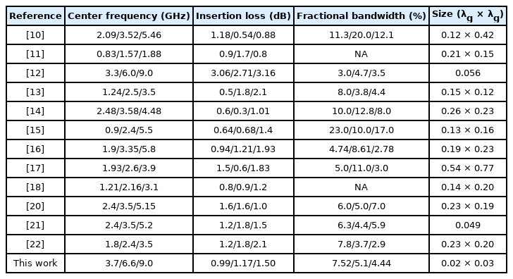
Comparison between the proposed model with other recent tri-band filters
IV. Conclusion
In this paper, a highly miniaturized triple-band BPF utilizing a pair of asymmetric SIRs with one step discontinuity and a UIR that shows a good tri-band response at 3.7 GHz, 6.6 GHz, and 9 GHz with a 3-dB FBW of 7.52%, 5.1%, and 4.44%, is designed and implemented through an electromagnetic simulation and experiments for WiMAX and RFID applications. The filter can be tuned by choosing the appropriate impedance ratio (R) and physical length ratio (α) of the asymmetric SIRs. The experimental results matched well with the measured results. Moreover, the measured results indicate that the presented tri-band BPF has a wide bandwidth, low insertion loss, and compact size and can be extensively applied in high-performance modern multiservice wireless communication systems.
References
Biography

Abdul Basit received a B.Sc. degree in Electrical Engineering in 2012 from the University of Engineering and Technology Peshawar, Pakistan, as a Communication was a major field, M.S. degree in 2013 from the CECOS University of IT and Emerging Sciences, Peshawar, Pakistan, and Ph.D. in Electrical Engineering from University of Engineering and Technology Peshawar, Pakistan, in 2021 under the supervision of Dr. Muhammad Irfan Khattak with a specialization in microwave filters. From 2013 to 2017, he was a lecturer in the Electrical Engineering Department of the University of Engineering and Technology, Peshawar, Pakistan. From 2017 to 2018, he served as an assistant director (technical) at National Transmission and Dispatch Company (NTDC). He is now working as a lecturer in the Electrical Engineering Department University of Engineering and Technology, Peshawar, Pakistan.

Muhammad Irfan Khattak worked as an associate professor in the Department of Electrical Engineering at the University of Engineering and Technology (UET), Peshawar. He received his B.Sc. in Electrical Engineering from the same university in 2004 and his Ph.D. from Loughborough University, UK, in 2010. After completing his Ph.D., he was appointed to Chairman of the Electrical Engineering Department at the UET Bannu Campus for 5 years and managed the academic and research activities in this department. Later, in 2016, he was appointed to the Campus Coordinator of the UET Kohat Campus and took over its administrative control. He also heads a research group called the Microwave and Antenna Research Group, where he supervises postgrad students working on the latest trends in antenna technology, such as 5G and graphene nano-antennas for THz, opto-electronic, and plasmonic applications. His research interests include antenna design, on-body communications, anechoic chamber characterization, and speech processing and speech enhancement. Besides his research activities, he is a certified OBE Expert with the Pakistan Engineering Council for organizing OBA-based accreditation visits.

Ayman Althuwayb received a B.Sc. degree (Hons.) in Electrical Engineering (Electronics and Communications) from Jouf University, Saudi Arabia, in 2011; a M.Sc. degree in electrical engineering from California State University, Fullerton, CA, USA, in 2015; and a Ph.D. degree in electrical engineering from Southern Methodist University, Dallas, TX, USA, in 2018. He is currently an assistant professor with the Department of Electrical Engineering at Jouf University, Kingdom of Saudi Arabia. His current research interests include antenna design and propagation, microwaves and millimeter-waves, wireless power transfer, ultrawideband and multiband antennas, and filters.

Jamel Nebhen received the M.Sc. in Microelectronics from the National Engineering School of Sfax, Tunisia in 2007, and the Ph.D. degrees from the Aix-Marseille University, France, in 2012, all in Microelectronics. From 2012 to 2018, he worked as a Postdoctoral Researcher in France in LIRMM-Lab Montpellier, IM2NP-Lab Marseille, ISEP Paris, LE2I-Lab Dijon, Lab-Sticc Telecom Bretagne Brest, and IEMN-Lab Lille. Since 2019, he joined the Prince Sattam bin Abdulaziz University in Alkharj, Saudi Arabia, as an Assistant Professor. His research interests are mainly in the design of analog and RF integrated circuits, IoT, biomedical circuit, and sensors instrumentation.