Cross-Pol Pattern Effects of Parabolic Reflector Antennas on the Performance of Spaceborne Quad-Pol SAR Systems
Article information
Abstract
The ambiguity performance related to the image quality of a synthetic aperture radar (SAR) system can be categorized into range ambiguity, azimuth ambiguity, and cross ambiguity depending on the cause of the ambiguity signals. The ambiguity performance is affected by the operational method and antenna radiation patterns of an SAR system. In this paper, the effect of the antenna cross-polarization (cross-pol) pattern on the ambiguity performance of a spaceborne quadrature polarimetric (quad-pol) SAR system using an X-band reflector antenna was analyzed. Two methods, conventional quad-pol SAR and hybrid quad-pol SAR systems, have been proposed as quad-pol SAR operational concepts for system performance analysis. We proposed a process to effectively analyze the effect of the antenna cross-pol pattern and showed this through a comparison of several analysis methods. In addition, the difference in antenna radiation patterns according to the size and structure of reflector antennas was compared, and the effects were described in detail. In conclusion, the larger the antenna and the more complex the structure, the greater the effect of the antenna cross-pol pattern, leading to a similar phenomenon as the two quad-pol SAR systems.
I. Introduction
A synthetic aperture radar (SAR) is a sensor that utilizes radio waves to obtain images with various information about the target to be observed according to the characteristics of the transmitted and received signals, that is, their frequency and polarization [1]. However, unlike a typical single polarization (single-pol) SAR system, the quadrature polarimetric (quad-pol) SAR system for obtaining multi-polarization images needs to be analyzed because the operational characteristics of the system greatly affect the quality of the images [2–4].
One of the most important performance indicators representing the quality of images obtained from the SAR system is the ambiguity-to-signal ratio (ASR). Ambiguous signals mainly consider the range direction component and the azimuth direction component, which are closely related to the elevation pattern and the azimuth pattern of the SAR antenna, respectively [5]. In addition to range and azimuth components, cross ambiguity has been considered [6, 7].
Polarimetric SAR (PolSAR) aims to detect the polarization change that occurs from the scattering mechanism on the target, but since the polarization of the signal can also be changed by the cross-polarization (cross-pol) component of the antenna, this undesired factor may have an influence on the system performance [8–11]. The antenna cross-pol pattern is generally caused by the asymmetry of the electric field on the antenna aperture plane, and in the case of a reflector antenna, it can be caused by the radiation pattern of the feeder or the shape of a reflector [12, 13]. Especially since the amplitude of an antenna cross-pol patterns tends to be larger as it moves away from the E/H-plane, it is necessary to take into account the effect of signals received from various directions.
In this paper, the ambiguity performance of the hybrid quad-pol SAR system as well as the conventional quad-pol SAR will be analyzed. In addition, the effect of the antenna cross-pol pattern on the ambiguity performance of a spaceborne quad-pol SAR system based on a parabolic reflector antenna will be compared and analyzed according to several types of antenna.
II. The Ambiguity Performance of SAR Systems
1. Ambiguity-to-Signal Ratio
System performance indicators related to SAR images include noise equivalent sigma zero (NESZ), resolution, and swath width. These performance indicators mainly consider the effects of the main beam of antenna radiation patterns, whereas the ambiguity ratios consider the overall shape of antenna radiation patterns, including sidelodes, so the ambiguity ratio is an important performance indicator that should be analyzed in SAR antenna design and optimization [14, 15]. If the ambiguity performance is not good enough, the signals coming into the sidelobes (i.e., the ambiguous signals) will result in artificial targets in the SAR image.
The range ambiguity considered in the range ambiguity-to-signal ratio (RASR), one of the expression methods of ASR, occurs when pulses transmitted at different times are received at the same time, and is expressed as [2, 16].
where Gt and Gr are antenna transmitting and receiving power patterns, respectively; σ0 is the backscattering coefficient; ρRA; is the range ambiguous slant range; θI is the incidence angle; θA, related to the slant range, is the angle at which the range ambiguity signals occur; m is a nonzero integer, meaning the order that precedes or succeeds the reference pulse in terms of the slant range; θAZ, related to the Doppler frequency, is the angle at which the azimuth ambiguity signals occur; and PB is the Doppler processing bandwidth. The integral with respect to PB was calculated based on the relation between the Doppler frequency and the azimuth angle.
The azimuth ambiguity considered in the azimuth ambiguity-to-signal ratio (AASR), the other expression method of ASR, occurs due to the finite sampling effect as much as the pulse repetition frequency (PRF) in the flight direction of the SAR platform, and is expressed as
where n is a nonzero integer, meaning the periodic order that is higher or lower than the Doppler centroid in terms of the azimuth frequency, and the other variables are the same as in Eq. (1). Generally, as the PRF of the SAR system increases, the RASR and AASR increases/decreases, respectively, and when the PRF decreases, the RASR and AASR decreases/increases, respectively [5]. In addition, as the antenna size increases, the ambiguity performance improves, but the resolution and swath width tend to be opposite. Therefore, it is necessary to select an optimal antenna size and system parameters to take this into account [15].
Cross ambiguity is a compound of the causes of range ambiguity and azimuth ambiguity, and accordingly, elevation and azimuth angles to the antenna boresight angle must be considered simultaneously. When Eqs. (1) and (2) are considered at the same time, the total ASR can be expressed as Eq. (3), and the cross ambiguity represents the case of both m ≠ 0 and n ≠ 0 [7]. The relation between each ambiguity component is shown in Fig. 1.
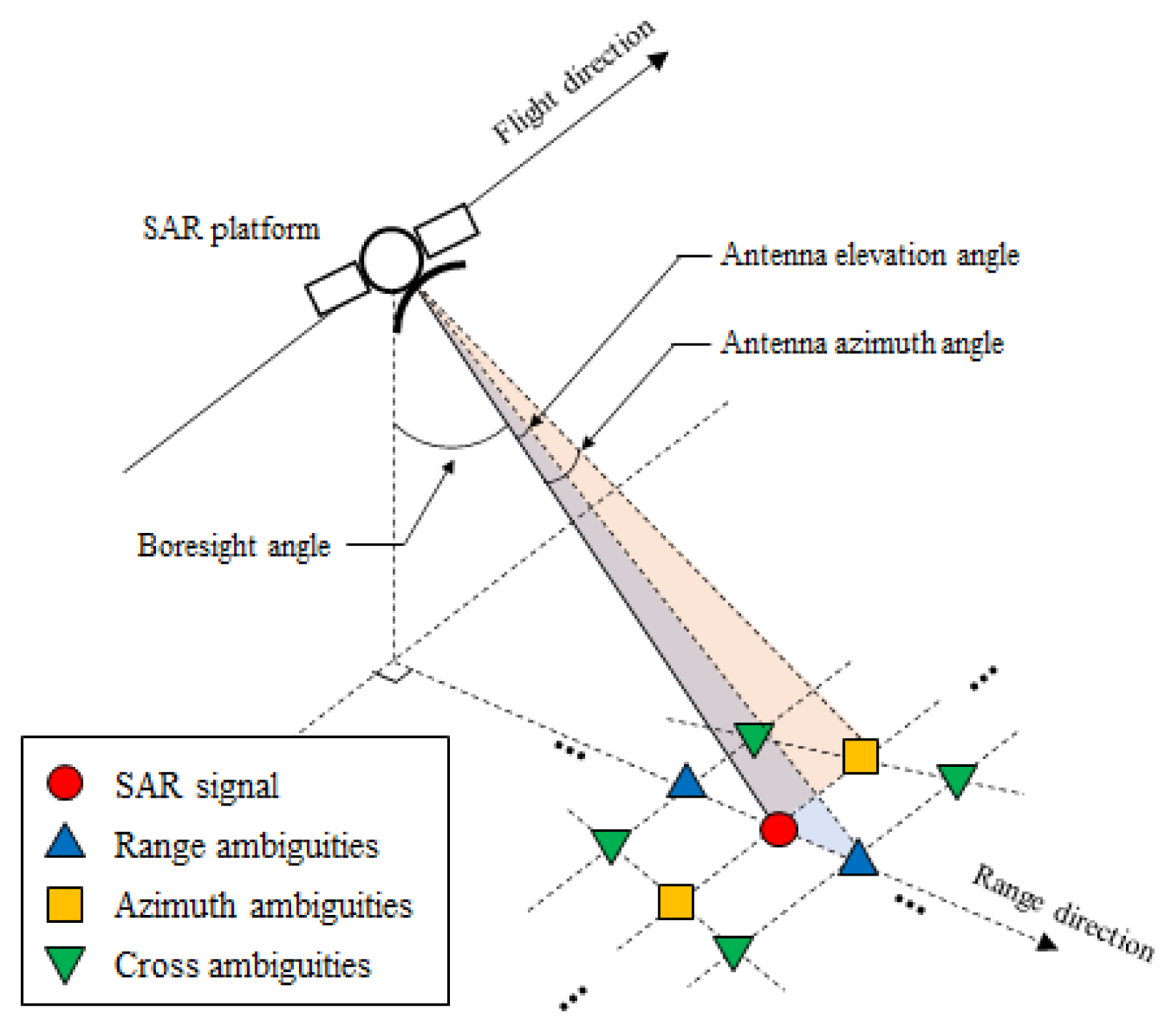
The relations between ambiguity components of the SAR system.
2. Polarimetric SAR Systems
The single-pol SAR system transmits and receives only signals with a single polarization, so that one polarization component, that is, one kind of σ0(θI), is used in the ambiguity performance analysis. However, since the conventional quad-pol SAR system alternates horizontal (H) and vertical (V) polarizations, two polarization components must be used when calculating RASR for four images, HH, HV, VH, and VV. When calculating RASR, since the backscattering coefficient of cross-pol channels such as HV and VH is smaller than that of co-polarization (co-pol) channels such as HH and VV, the RASR performance of the cross-pol channel is severely deteriorated [2–4].
Hybrid quad-pol SAR has been proposed as a method to compensate for this serious adverse effect [17, 18]. The hybrid quad-pol SAR operates to receive both H and V signals at each moment while alternating between RHCP (right-hand circular polarization) and LHCP (left-hand circular polarization) signals. A comparison of the operation methods for each SAR system is shown in Fig. A1.
Based on this operation, the hybrid quad-pol SAR system can obtain four signals, HR, HL, VR, and VL (SHQ), and can be transformed to signals obtained from conventional quad-pol SAR (SCQ) through the transformation relationship [18],
where the superscript ^ above S indicates after transformation. It is noticeable here that after the transformation, the RASR calculation of each polarization channel only considers its effect on that polarization [17]. In other words, the effect of the copol signal, which is relatively larger than the cross-pol signal due to the difference of the backscattering coefficient, disappears.
However, because there is a time gap between the elements of SHQ that are combined to obtain a signal for SCQ, a phase difference occurs in the spectrum, and this does not completely cancel the unwanted components [2]. In the case of the HV signal as an example, according to Eq. (4)
and
where the superscript ~ indicates a sampled signal and T is the time interval between transmitted signals of the same polarization [2]. The Fourier transform of Eq. (6) yields the spectral relational equation in Eq. (7) (scale factors were ignored). Therefore, even if these two signals are summed, neither can cancel out, which can be expressed as shown in Fig. 2.
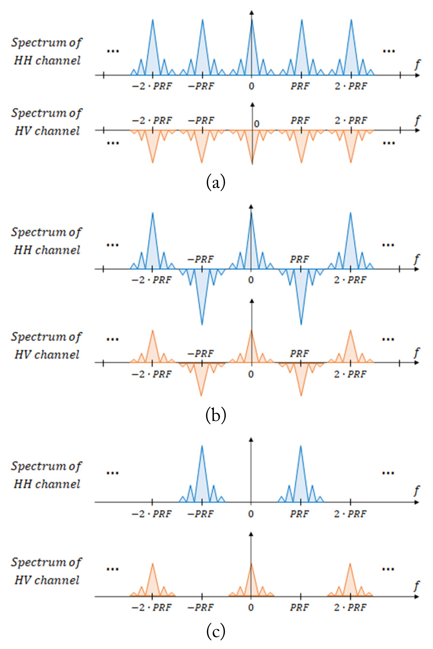
Composition process of hybrid quad-pol SAR signals for the SHV case; (a) S̃HR, (b) S̃HL, and (c) S̃HV = jS̃HR / 2 − jS̃HL / 2.
This phenomenon also occurs for the other three signals. Therefore, similar to RASR in conventional quad-pol SAR, in hybrid quad-pol SAR, two polarized signals must be considered when calculating AASR, which degrades the ambiguity performance of cross-pol channels. The operational method of alternately transmitting orthogonal waveforms like the ±π/4 mode [19] produces the same result [2, 18, 20].
When we consider the characteristics of the conventional quad-pol and hybrid quad-pol, which means the ambiguous polarization components alternately interleaved in the range direction in the conventional quad-pol and the azimuth direction in the hybrid quad-pol, Eq. (3) can be modified and concisely expressed above in Eq. (8). Here, the subscript t is the transmitted polarization, r is the received polarization, and t̄ is the orthogonal signal of t. For example, if t is H, then t̄ is V. After this, the ambiguity performance analysis was performed based on Eq. (8).
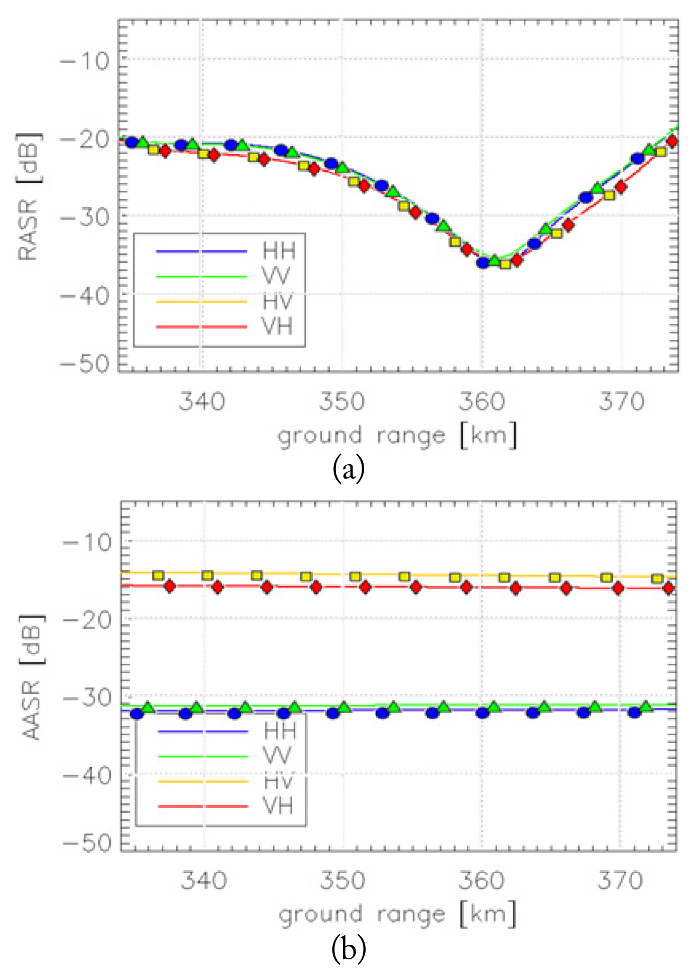
The calculation of the ambiguity ratio for the conventional quad-pol SAR system had already verified [3], and in this paper, additional verification for the hybrid quad-pol SAR system was carried out. Fig. 3 shows the results of calculation and comparison based on the system parameters of the L-band stripmap SAR system given in [2], which shows the performance of the hybrid quad-pol SAR system.
3. Effects of Antenna Cross-Pol Pattern
The cross-pol signal obtained from PolSAR covered in Section II-2 considers the case where the change in polarization occurs only in the target. That is, since there is only one possible polarization change, there are only two cases in which the same received polarization is achieved through different processes. This result is also expressed by Eq. (8). However, in reality, a change in polarization occurs in the antenna as well, which contributes to the degradation of system performance; this is not intended. The contribution of the antenna to the polarization change is represented by the antenna cross-pol pattern. Therefore, if the polarization change caused by the transmitting and receiving antennas is considered, eight possible cases can be assumed as a total [8]. Based on Eq. (8), there are currently
III. Performance Analysis and Comparison of Spaceborne SAR System
1. Spaceborne SAR System Using an X-Band Parabolic Reflector Antenna
As the SAR antenna for the performance analysis of the X-band spaceborne SAR system operating in stripmap mode at an altitude of 500 km, a solid panel deployable type reflector antenna, as shown in Fig. 4, was used [21]. This reflector consists of 30 panels, a ratio of the diameter between the main reflector and flat central disk of 0.133, and a focal-length-to-diameter ratio of 0.3. The antenna far-field pattern was obtained using the FEKO simulation tool’s MLFMM (multilevel fast multi-pole method) analysis method.
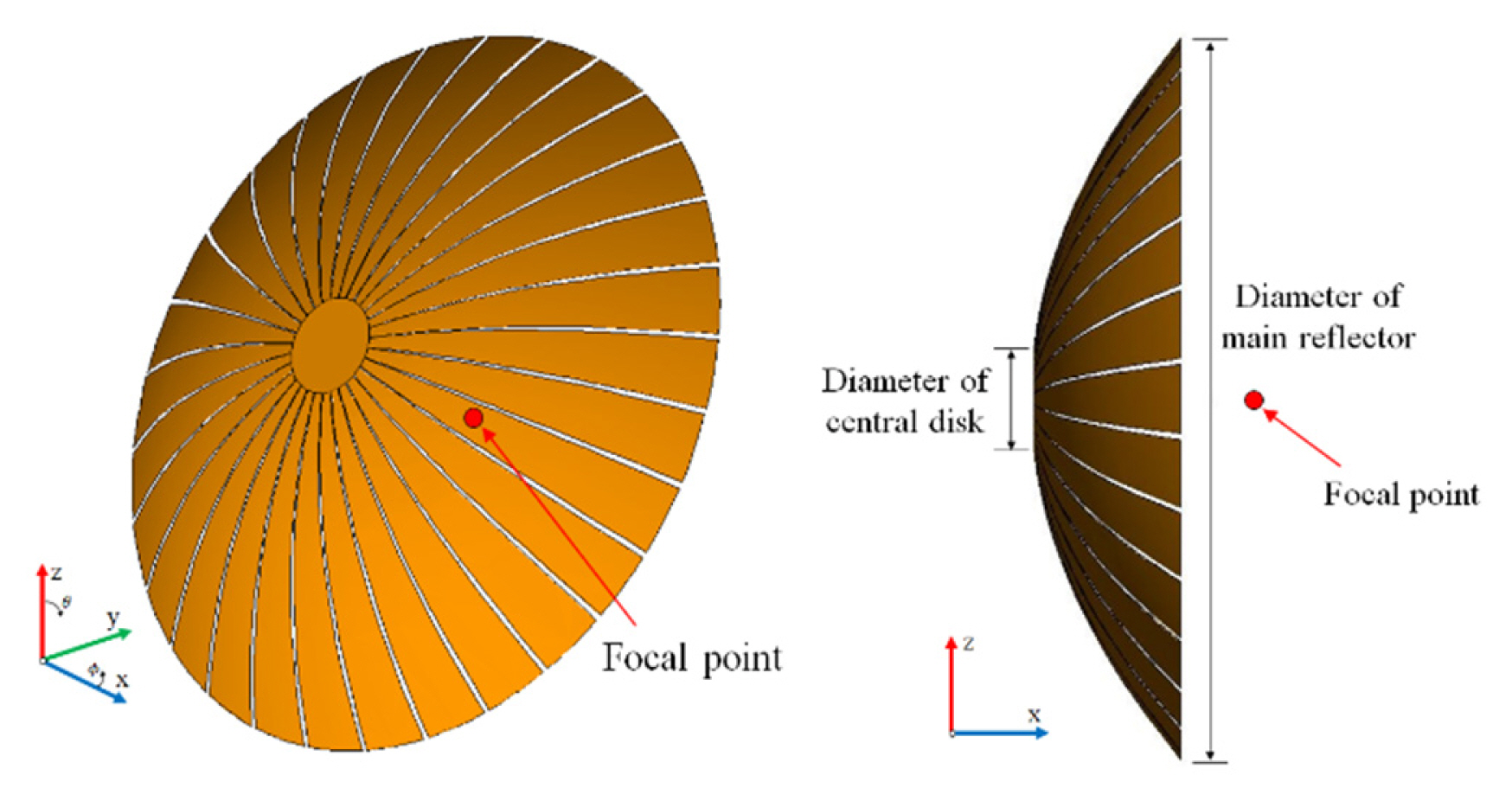
Configuration of the simulated reflector antenna with panels.
In this paper, three representative antennas were selected for the effect analysis of the antenna cross-pol pattern on ambiguity performance. One is a small reflector antenna with a diameter of 1.5 m and a Gaussian beam pattern of −12 dB edge taper was used as the radiation pattern of the feeder. This feeder was mathematically defined by using the function of a simulation tool. In addition, a reflector antenna with a diameter of 3 m and the same feed pattern was used as another case for system performance analysis. The structure of this large antenna is scaled-up in Fig. 4. Finally, in order to evaluate the effect of the feeding structure and struts, a simulation including scatterers was performed in the case of 3 m in diameter. Fig. 5 is the configuration of a large reflector antenna with a diameter of 3 m considering the feeding structure. A detailed description of this antenna structure is shown in [21] for the case of a small antenna.

Configuration of the reflector antenna including the feeding structure.
The simulated results of the far-field pattern at 9.6 GHz are shown in Figs. 6 and 7. The gain of the small antenna, shown in Fig. 6, satisfies the performance of 40 dB and the sidelobe level of −20 dB for the elevation and azimuth patterns. Fig. 7 shows the simulation results of the antenna radiation pattern before and after considering the feeding structure. The performance of two antennas with a reflector diameter of 3 m satisfies a gain of 46 dB and a sidelobe level of −20, but as the feeding structure was considered, the sidelobe increases not only in the antenna co-pol pattern, such as gain and sidelobe, but also in the antenna cross-pol pattern. It is thought that this result could lead to degradation in the ambiguity performance of the SAR system.
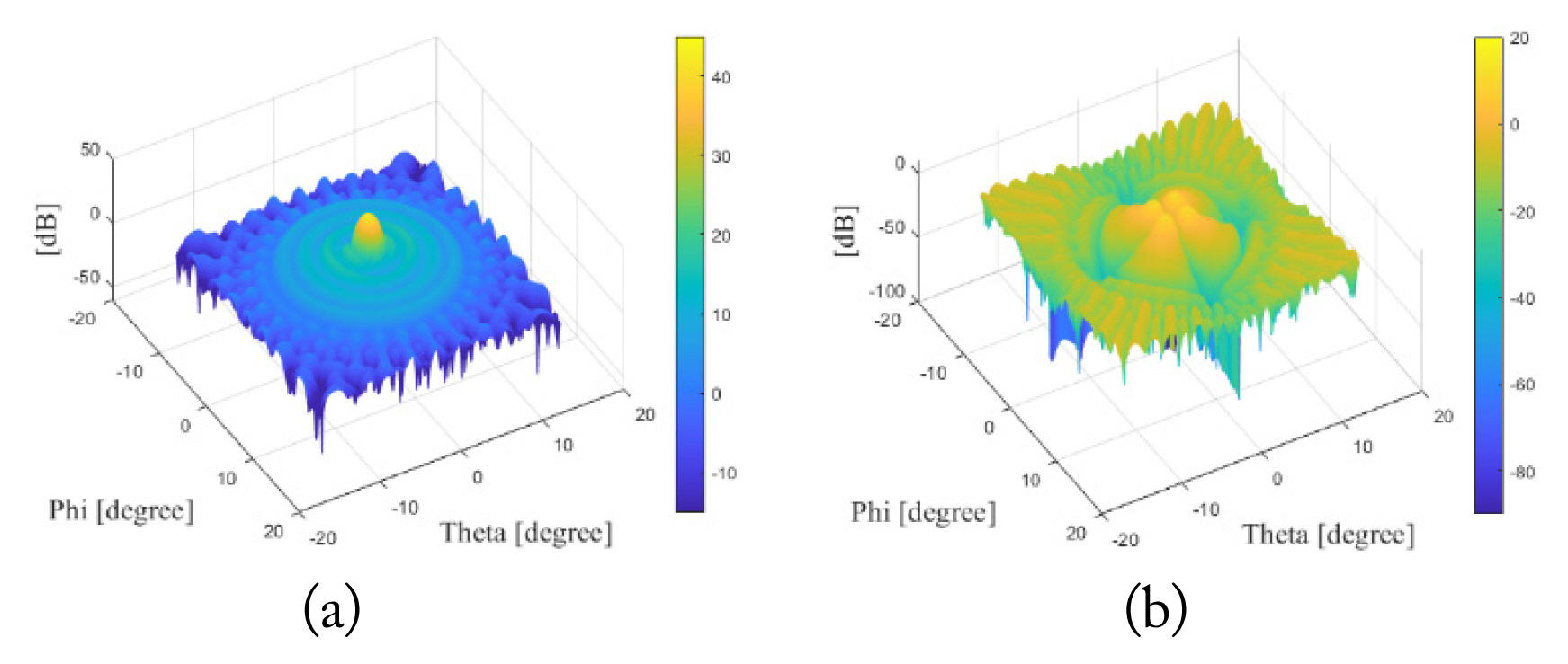
Simulation results of the antenna far-field pattern: (a) copol pattern and (b) cross-pol pattern.
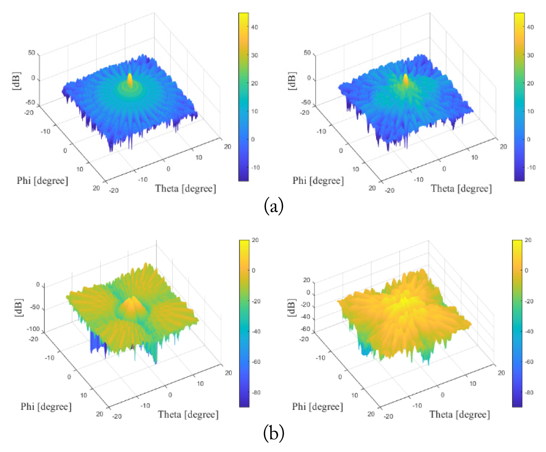
Comparison of the antenna far-field pattern. Left is the case of the reflector only and right is the case of considering the feeding structure: (a) co-pol pattern and (b) cross-pol pattern.
A brief comparison of the antenna cross-pol performance of these three antennas shows that the last case, which considers the effect of the feeding structure, is the worst. When only the main reflector is considered for antenna analysis, a 3 m reflector with a large antenna size performs best, and a 1.5 m reflector has a moderate performance.
Figs. 6 and 7 shows the results for the V-polarization (V-pol) pattern, which means that the feed antenna transmits and receives polarized waves in a z-direction, but both the V-pol and the H-polarization (H-pol) patterns are required to analyze the ambiguity performance of the quad-pol SAR system. However, in the case of two antennas where only the reflector is considered, the V-pol and H-pol patterns are similar in terms of their effect on the ambiguity ratio, and the reflector antenna containing the feeding structure is enough to account for performance variations caused by struts, even if only the V-pol pattern is considered. Therefore, in this paper, we assumed that the V-pol pattern and H-pol pattern are the same in the analysis of ambiguity performance.
2. Analysis Results of the Ambiguity Performance
Generally, when considering the backscattering coefficient, the ambiguity performance for the co-pol channel is better than that for the cross-pol, so this paper only dealt with the performance for the cross-pol channel, i.e., the HV channel.
The PRF and observation region for the system performance analysis using a small antenna with a diameter of 1.5 m were selected in consideration of the timing diagram shown in Fig. 8 and the RASR and AASR in the HV channel. In this case, assuming the use of the hybrid quad-pol SAR system, the PRF requirement for AASR improvement increases considerably, so only the case of a conventional quad-pol SAR was covered when using a small antenna.
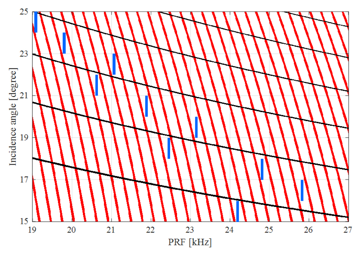
Timing diagram of the spaceborne SAR system using a small antenna. Red lines are blind range; black lines, nadir return; blue segments, PRF selection.
The ambiguity ratio calculation was performed for three cases to confirm the effect of cross ambiguity and the antenna cross-pol pattern through comparisons between these cases. In Case 1, range ambiguities and azimuth ambiguities were added only, i.e., either m or n is always zero in Eq. (8). In this case, the effect of the antenna cross-pol pattern was not considered. In Case 2, the cross ambiguity component was added to Case 1, and the effect of the antenna cross-pol pattern was not considered in this case either. In other words, Case 2 is calculated from Eq. (8). In the third case, Case 3, the effect of the antenna cross-pol pattern was additionally considered on Case 2, which means that Eq. (8) should be modified by reflecting the technical description covered in Section II-3.
The results for each case are shown in Fig. 9. At the overall incidence angle, the RASR and AASR performances were not good enough, as the antenna was small. In addition, the effects of the cross ambiguity and antenna cross-pol pattern were relatively small in the large incidence angle compared to those in the small incidence angle. It is conjectured from the results shown in Fig. 9 that when RASR and AASR are improved, the effects of cross ambiguity and the antenna cross-pol pattern will be detectable.
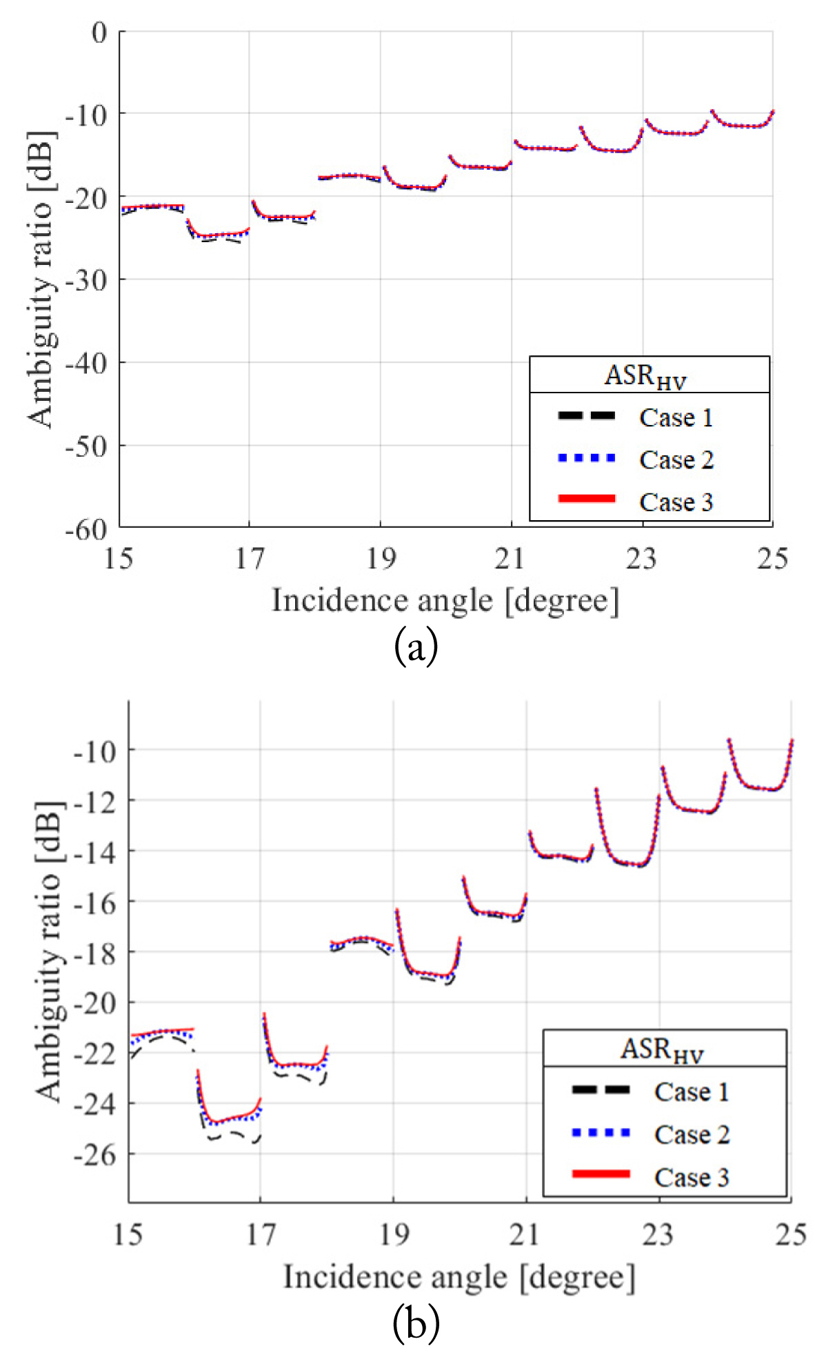
Analysis results of the ambiguity performance of the spaceborne SAR system using a small antenna: (a) comparison of the ambiguity performance and (b) zoom in. Black lines are Case 1; blue lines, Case 2; red lines, Case 3.
The following is a performance analysis for the reflector antenna with a diameter of 3 m. First, system parameters based on the antenna radiation pattern without the feeding structure were selected. In order to compare conventional quad-pol SAR and hybrid quad-pol SAR, a PRF was selected that made RASR and AASR, which were considerably degraded components in each system, similar. This result is shown in Fig. 10.
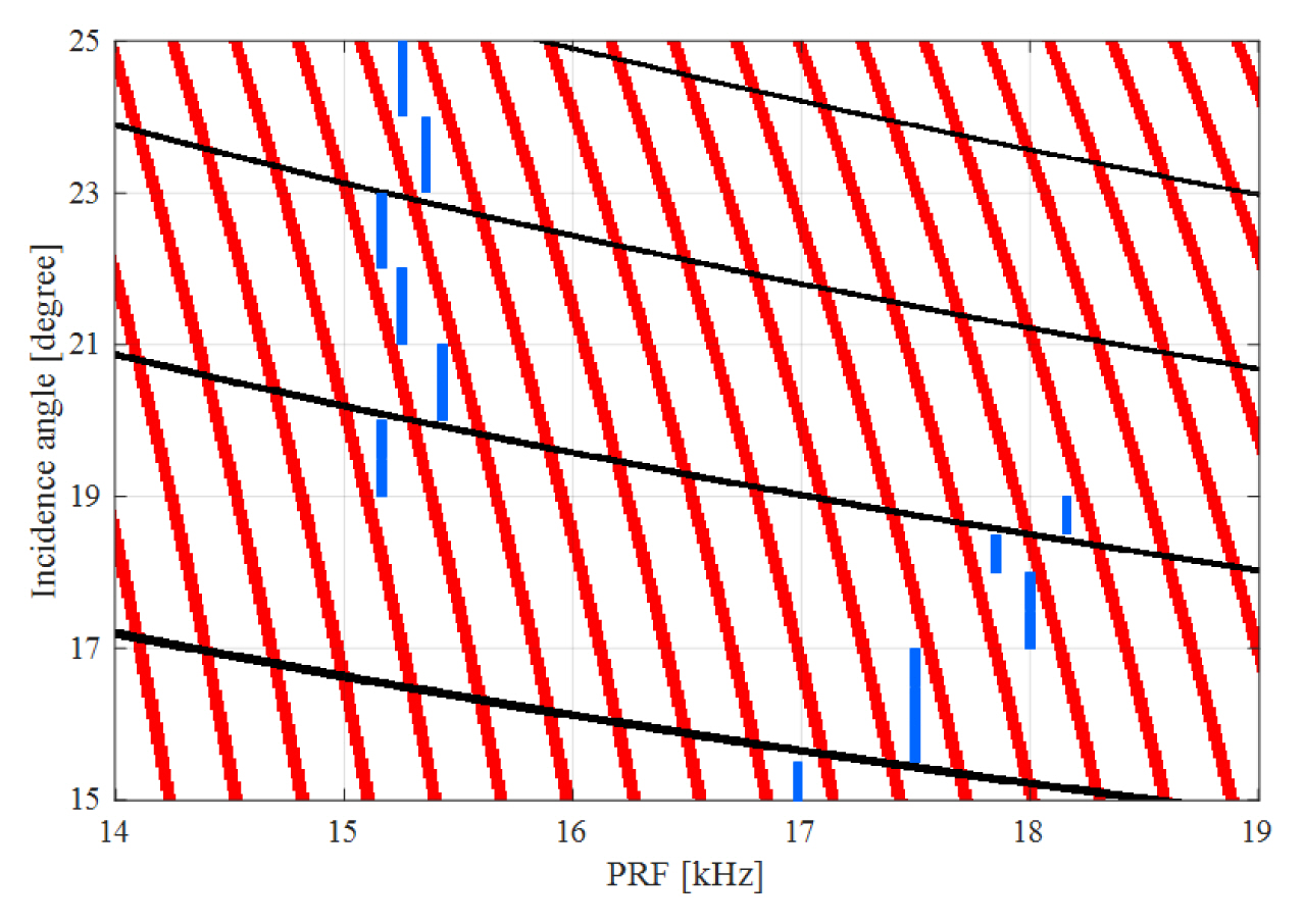
Timing diagram of the spaceborne SAR system using a large antenna. Red lines are blind range; black lines, nadir return; blue segments, PRF selection.
For comparison with the case of using the small antenna shown in Fig. 9, the total incidence angle was maintained in the same range as in this analysis. However, since the antenna beamwidth was smaller than the small antenna, each observation region was further subdivided. Based on this, the results of analyzing the ambiguity performance of the spaceborne quad-pol SAR system are shown in Figs. 11 and 12.
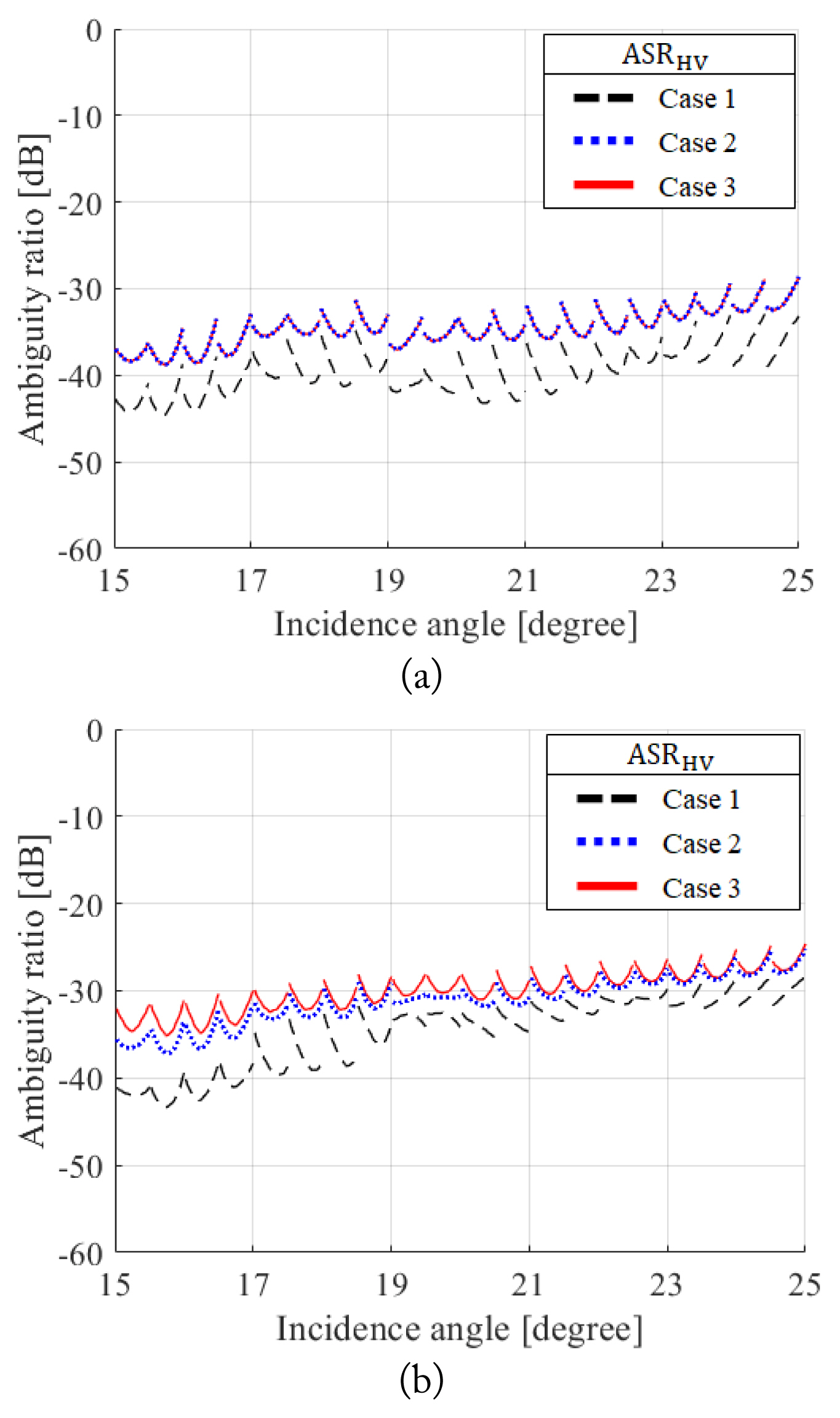
Analysis results of the ambiguity performance of the conventional quad-pol SAR system: (a) reflector only and (b) considering the feeding structure. Black lines are Case 1; blue lines, Case 2; red lines, Case 3.
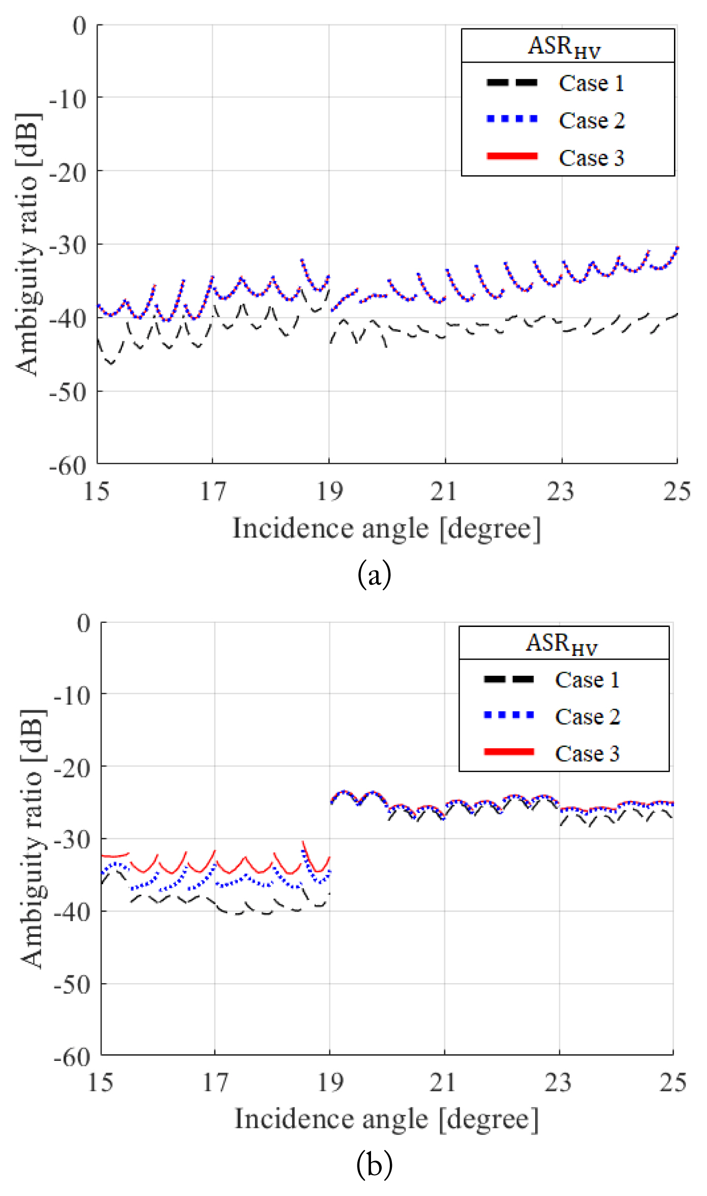
Analysis results of the ambiguity performance of the hybrid quad-pol SAR system: (a) reflector only and (b) considering the feeding structure. Black lines are Case 1; blue lines, Case 2; red lines, Case 3.
Comparing the performance degradation that resulted from the conventional method, Case 1, it can be seen that the additional pattern-deteriorating factors can lead to significant performance degradation. In particular, through the proposed analysis method, Case 3, which considers the effect of the antenna cross-pol pattern, a rigorous analysis considering severe conditions caused by various factors will be performed. Fig. 11 shows the result of the conventional quad-pol SAR system, and it can be seen from Fig. 11(a) that the effect of cross ambiguity was relatively large compared to the case of using a small antenna. However, the red lines and the blue lines seen above are almost matched, which means that the effect of the antenna cross-pol pattern was still hardly seen. From Fig. 11(b), which is the result of including the feeding structure of the reflector antenna in the simulation, the RASR and AASR performance were degraded due to the feeding structure, and the effect of the antenna cross-pol pattern begins to appear as a non-negligible amount. This result shows a difference of up to about 8 dB when compared to Case 1 and up to about 3 dB when compared to Case 2 in terms of the ambiguity performance of the SAR system.
As shown in Fig. 12, the same results were observed in the hybrid quad-pol SAR system. Therefore, the effect of the antenna pattern variation due to the feeding structure on the performance of PolSAR systems such as conventional quad-pol SAR and hybrid quad-pol SAR can be analyzed by considering the effect of the antenna cross-pol pattern. Additionally, considering the cross ambiguity together was effective in confirming the effect of the antenna cross-pol pattern.
In summary, when the RASR and AASR of the SAR system were not sufficiently good, such as when a small antenna was used, additional factors, such as cross ambiguity, need not be considered. However, if the RASR and AASR are improved, the cross ambiguity should also be considered. In particular, when there were factors that increased the antenna cross-pol pattern, considering these effects will be more helpful for accurate system performance analysis.
IV. Conclusion
In this paper, the effect of the antenna cross-pol pattern on the ambiguity performance of the spaceborne quad-pol SAR system was analyzed. For conventional quad-pol SAR and hybrid quad-pol SAR, the ambiguity ratio calculation process was introduced and the effect of the antenna cross-pol pattern was compared according to the antenna size. When the size of the antenna is large, the structure is complex, and there is a possibility that asymmetry increases, the effect of the antenna cross-pol pattern on the ambiguity performance of the SAR system becomes significant enough that it cannot be ignored. Thus, it can be seen from the results that the effect of the antenna cross-pol pattern is enough to require serious analysis. This trend appears to be the same in both the conventional quad-pol SAR and hybrid quad-pol SAR, which go through different operation methods and analysis processes.
In terms of the relation between the antenna cross-pol pattern and the performance of the SAR system, ambiguity analysis is required not only in the structure in which the effects of scattering objects such as struts and feed antennas appears but also when the reflector has an asymmetric structure, such as an offset type.
Although the ambiguity performance (RASR and AASR) of a large antenna is basically good, so that the effect of the antenna cross-pol pattern does not conflict with the system requirements, it is expected that the effect of the antenna cross-pol pattern can be utilized for the optimal design of an antenna with a complex structure.
Acknowledgments
This work was supported by the National Research Foundation of Korea (NRF) grant funded by the Korea government (MIST) (No. 2019R1F1A1060241).
References
Appendices
Appendix
Fig. A1 shows basic system operational concepts. Time interval, T shown in Eqs. (6) and (7), was calculated in the manner shown in this figure.
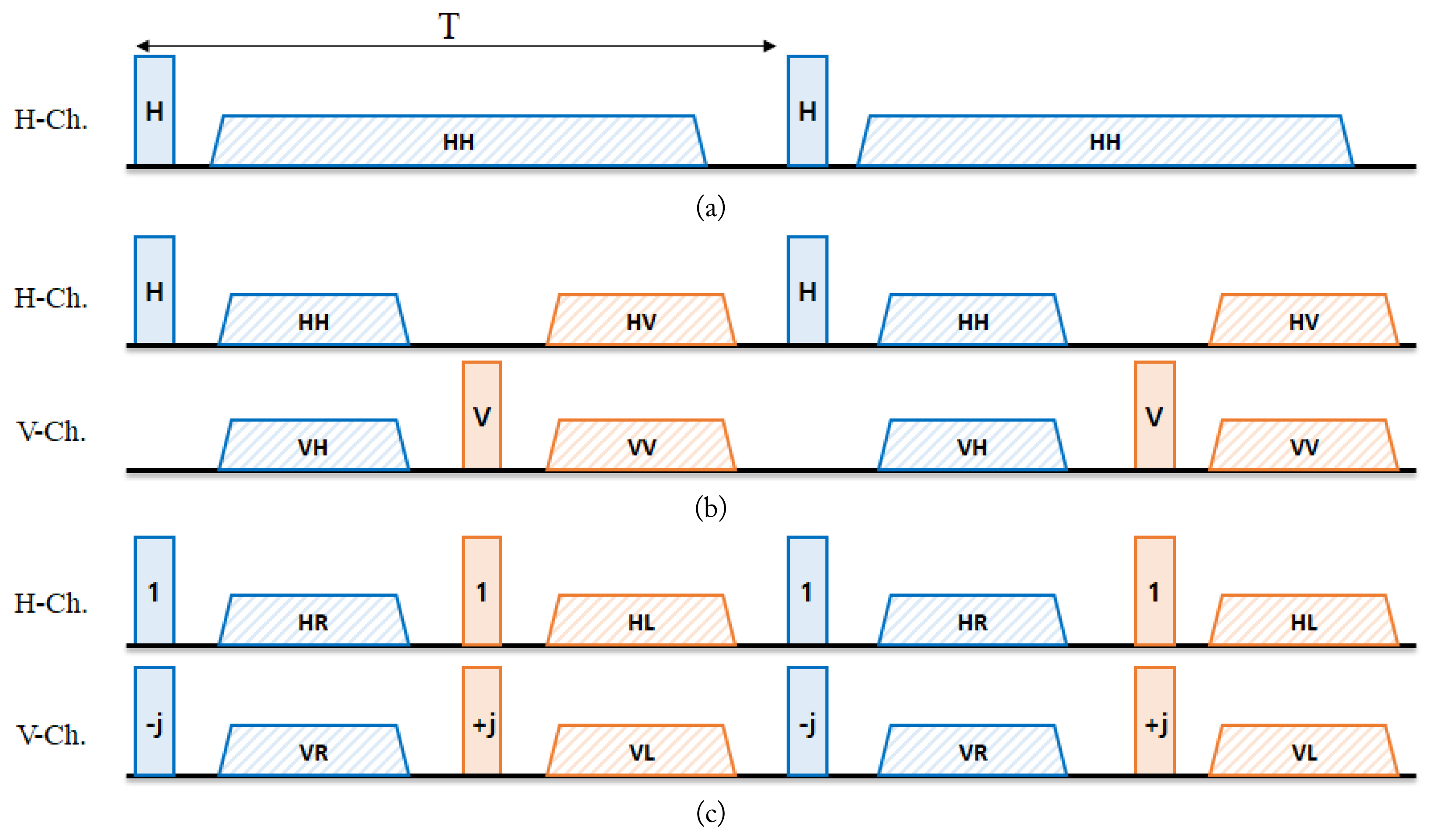
Timing diagram of the SAR systems: (a) single-pol SAR system, (b) conventional quad-pol SAR system, and (c) hybrid quad-pol SAR system. Colored rectangles are transmitting pulses and patterned trapezoids are receiving pulses.
Biography

Jung-Hwan Lim received his B.S. and M.S. degrees in electronics and information engineering from Korea Aerospace University (KAU), Goyang, Korea, in 2018 and 2020, respectively. He is currently working toward a Ph.D. degree at the Microwave and Millimeter-wave Solution Laboratory of KAU. His current research interests include satellite communications/radar antennas, spaceborne SAR systems, and EMI/EMC.

Jae Wook Lee received his B.S. degree in electronic engineering from Hanyang University, Seoul, Korea, in 1992, and his M.S. and Ph.D. degrees in electrical engineering with a specialization in electromagnetics from the Korea Advanced Institute of Science and Technology, Daejeon, Korea, in 1994 and 1998, respectively. From 1998 to 2004, he was a senior member of the Advanced Radio Technology Department, Radio and Broadcasting Research Laboratory, Electronics and Telecommunications Research Institute, Daejeon. He was with the faculty of the Korea Aerospace University (KAU), Goyang, Korea. He is currently a professor at the School of Electronics and Information Engineering of KAU. His current research interests include high-power amplifier design, computational electromagnetics, electromagnetic interference/electromagnetic compatibility analysis on printed circuit boards, satellite antennas, and spaceborne SAR systems.

Taek-Kyung Lee received his B.S. degree in electronic engineering from Korea University, Seoul, Korea, in 1983, and his M.S. and Ph.D. degrees in electrical engineering from the Korea Advanced Institute of Science and Technology (KAIST), Daejeon, Korea, in 1985 and 1990, respectively. From 1990 to 1991, he was a post-doctoral fellow at the University of Texas at Austin, TX, USA, under a grant from the Korea Science and Engineering Foundation. From 1991 to 1992, he was a research scientist at KAIST. In 1992, he joined the faculty of Korea Aerospace University (KAU), Goyang, Korea. He was an associate visiting research professor at the University of Illinois at Urbana–Champaign, IL, USA, from 2001 to 2002. From 2006 to 2007, he was the chairman of the School of Electronics, Information, and Computer Engineering at KAU, where he was the director of the Aerospace and Aviation Electronics Research Center, from 2011 to 2013. He was the Chairman of the Radar Technical Group, Korean Institute of Electromagnetic Engineering and Science, Seoul, from 2012 to 2013, and he served as the president of this institute in 2014. He is currently a professor at the School of Electronics and Information Engineering, KAU. His current research interests include computational electromagnetics, antennas, microwave passive circuits, satellite antennas and spaceborne SAR systems, and air surveillance systems.