A Dual-Band Low-Power-Consumption Active RFID Tag Based on a Meander FPCB Antenna for Subway Vehicle Management
Article information
Abstract
A meander microstrip antenna was designed to operate in the UHF and microwave bands. Laser direct structuring (LDS) and the flexible printed circuit board (FPCB) method were used to fabricate the antenna, and their results were compared. A dual-band low-power-consumption active radio frequency identification (RFID) tag based on the present antenna was developed and fabricated for an automated subway vehicle maintenance system. The recognition distance of the active tag is more than 20 m at 900 MHz and more than 170 m at 2.4 GHz, while the recognition rate is >95% at 900 MHz and 100% at 2.4 GHz. The 100% recognition rate was obtained when the RFID readers were placed in a line parallel to the subway track. Therefore, we have shown that our active RFID tag can be used in a subway vehicle management system.
I. Introduction
Radio frequency identification (RFID) technology enables identification from a distance and can discern numerous tags located in the same area without human assistance and without requiring a line of sight [1–4]. In recent years, this technology has moved into mainstream applications, such as metro tickets and contactless payments. The communication between an RFID reader and a tag depends on the frequency band used by the tag [5]. In the low-frequency band (120–150 kHz) and high-frequency band (13.56 MHz), tags should be placed very close to the reader antennas. For example, high-frequency RFID tags have a read range of about 30 cm. Meanwhile, tags operating at UHF and higher frequencies function at more than 30 m away from the reader and can backscatter a signal. For simultaneous near-field and far-field operations, we developed a dual-band RFID tag based on a meander antenna operating in the UHF band (917–923 MHz) and microwave band (2.4–2.45 GHz).
Meander line technology allows for the design of a small antenna with wideband performance [1, 6, 7]. In addition, the flexible printed circuit board (FPCB) is largely used in electronics manufacturing and is always in need of a higher level of integration. Over the years, the technology has been widely improved, and it shows promise in a diversity of application fields, including antennas, due to its light weight, compact size, and cost effectiveness when compared to traditional rigid printed circuit boards [8, 9]. For these reasons, we developed and fabricated a meander microstrip antenna using traditional laser direct structuring (LDS) and the novel FPCB technology and compared the two fabrication methods. In the present paper, we report on a compact dual-band low-power-consumption active RFID tag. The structure of a dual-band meander FPCB antenna is discussed in Section II, followed by the specifications of a dual-band low-power-consumption active RFID tag in Section III. In Section IV, we describe the field tests using the designed tags, while some final conclusions are provided in Section V.
II. A Dual-Band Meander FPCB Antenna
An antenna working in the UHF (917–923 MHz) and microwave bands (2.4–2.45 GHz) with the help of a meander line for size reduction was designed and fabricated for an RFID-based subway car maintenance system. The structure and design of the dual-band antenna inspired by meander lines is illustrated in Fig. 1.
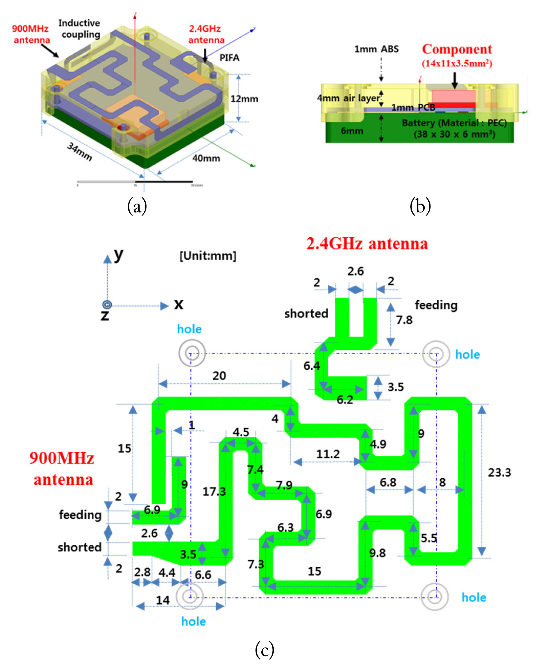
Layout of the dual-band meander microstrip antenna: (a) 3D view, (b) side view, and (c) top and overall unfolded antenna.
Fig. 1(a) and (b) show the structure and Fig. 1(c) the overall unfolded schematic and dimensions of the radiator of the proposed design. The antenna consists of radiators and a ground plane, which comprises a battery (32 mm × 38 mm × 6 mm), PCB (32 mm × 38 mm × 1 mm; the component mounted on the PCB is metallic), and dielectric layer (composed of an air and ABS layer). The layer). The overall size of the antenna is 34 mm × 40 mm × 12 mm. The radiators are designed on the ABS (ɛr = 2.2, thickness = 1 mm) and FPCB (ɛr = 2.3, copper layer mass = 1 oz, thickness = 0.025 mm). The antenna proposed for the UHF band uses an inductive coupling feeding and loop antenna structure, while the one for the microwave band adopts the folded planar inverted-F antenna (F-PIFA) structure.
As shown in Fig. 2, the meander microstrip antennas were fabricated using FPCB and LDS. The dimensions and shapes of the meander lines were optimized through a tuning process to achieve the targeted frequency bands and characteristics.
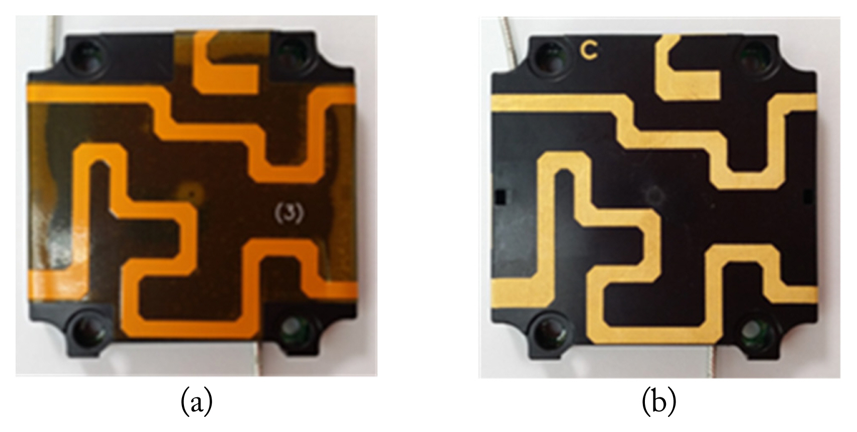
The fabricated dual-band meander microstrip antennas: (a) FPCB and (b) LDS.
Fig. 3 shows the simulated and measured S-parameters of the proposed dual-band antenna. The resonance frequency of the FPCB antenna is 1,030 MHz and that of the LDS antenna is 1,050 MHz. As seen in the figure, the LDS antenna’s spectrum differs more from the simulation than the FPCB S-parameters do.

The S-parameters of the proposed antenna.
Fig. 4 shows the frequency characteristics of the proposed dual-band antenna using FPCB technology after tuning. The antenna for the UHF band using FPCB has the resonance frequencies of 920 MHz and 2,550 MHz. The antenna proposed for the microwave band using FPCB technology has resonances at 2.37 GHz and 2.57 GHz. The voltage standing wave ratio of the dual-band antenna is VSWR = 2:1 for the operating UHF and microwave bands. The isolation between the antennas for the UHF and microwave bands reached over 10 dB for all operating bands.
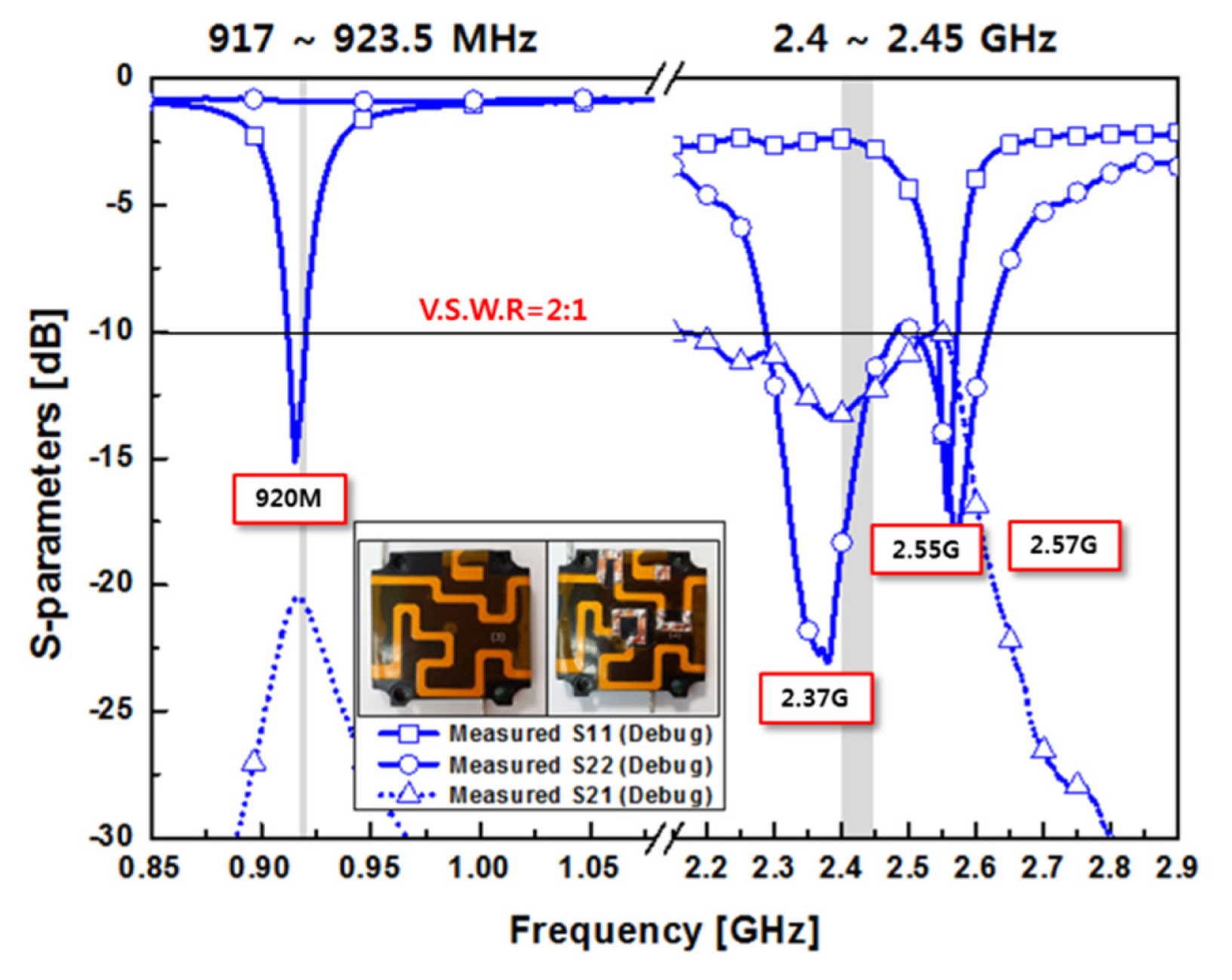
The measured frequencies of the proposed antenna (FPCB).
The tuning was performed in the same way for both types of antennas. Fig. 5 shows the overall unfolded dimensions after tuning: the electrical length of the UHF antenna was extended by 34.2 mm and that of the microwave antenna by 2.9 mm.

The overall unfolded dimensions after tuning.
The dimensions were optimized through tuning to achieve the target frequency band and characteristics of the proposed dual-band antenna. However, LDS has a high rate of change in frequency due to changes in electrical length, resulting in large input terminal coupling losses and impedance mismatch losses due to process errors.
The proposed dual-band antennas were measured in an anechoic chamber (10 m × 10 m × 4 m). To accurately measure small antennas (like the ones we propose), the metallic ground effect on them has been studied [10, 11]. In this paper, we used a 100 mm × 100 mm metallic ground for the measurements.
Fig. 6 shows the radiation pattern of the proposed dual-band antenna using FPCB technology. The antenna for the UHF band has a maximum gain of 2.65 dBi at 920 MHz, while the antenna for the microwave band has a maximum gain of 4.49 dBi at 2,425 MHz.
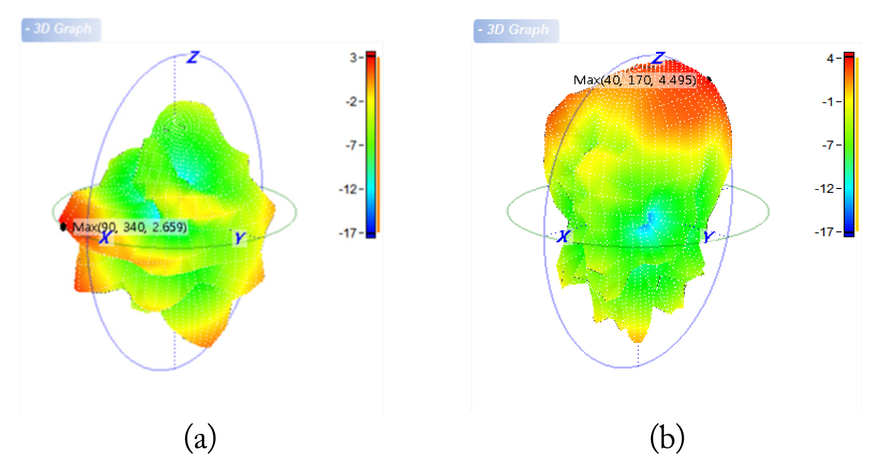
The measured radiation pattern of the proposed FPCB antenna.
Fig. 7 shows the measured gain values of the dual-band meander microstrip antennas. As shown, the gains of the LDS antenna are 0.47 dBi to 1.43 dBi over the UHF band and 2.88 dBi to 3.65 dBi over the microwave band. The FPCB antenna has gains of 1.95 dBi to 3.10 dBi for the UHF band and 4.37 dBi to 4.57 dBi for the microwave band. Therefore, the gain of the FPCB antenna is greater than that of the LDS antenna.
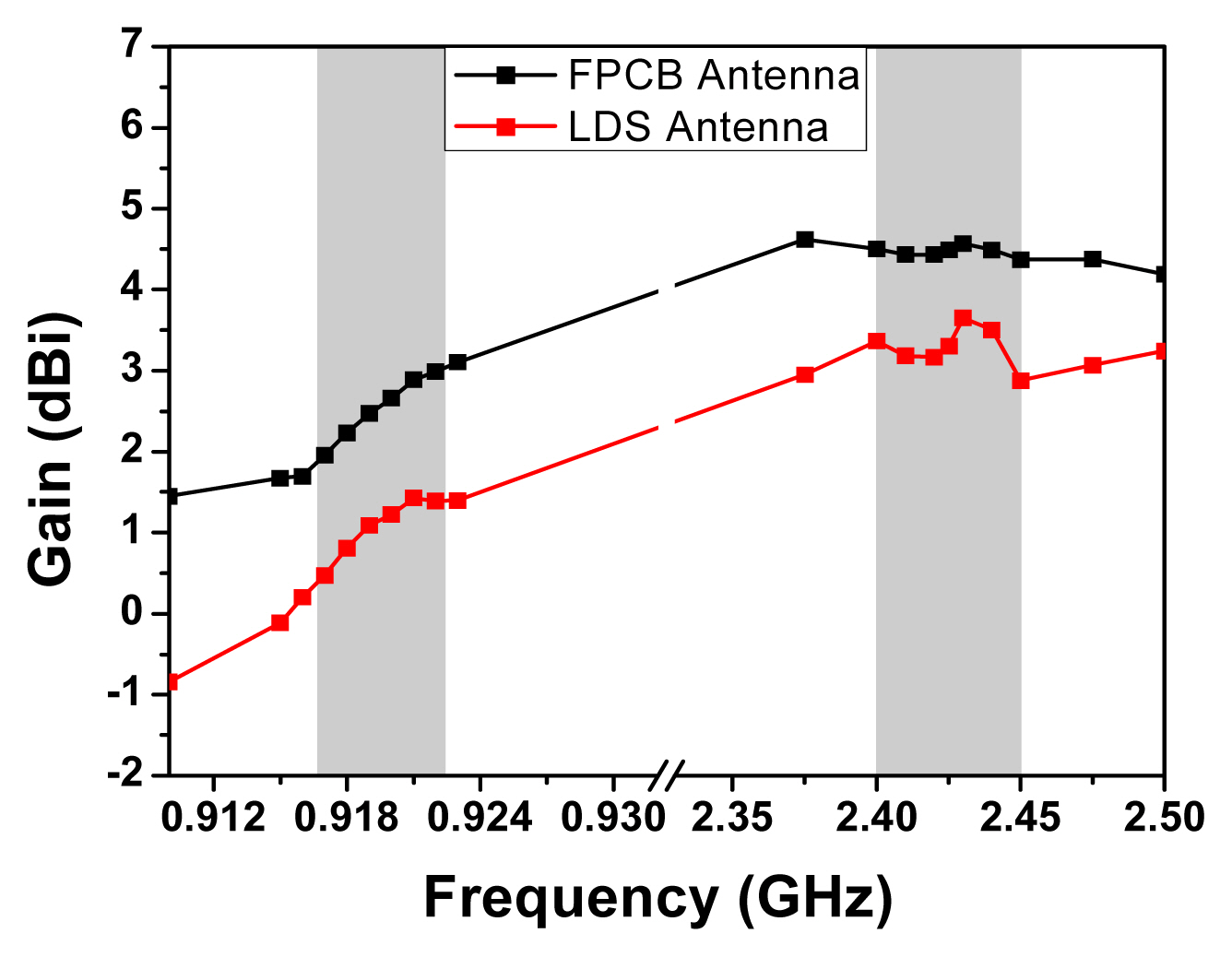
Comparison of the gain values of the FPCB and LDS antennas.
Fig. 8 illustrates the measured efficiency values of the dual-band meander microstrip antennas. As shown, the efficiencies of the LDS antenna are more than 30% in the UHF band and more than 35% in the microwave band. The antennas were optimized to have maximum efficiency (62% for FPCB and 42.48 % for LDS) at 2,430 MHz specifically.
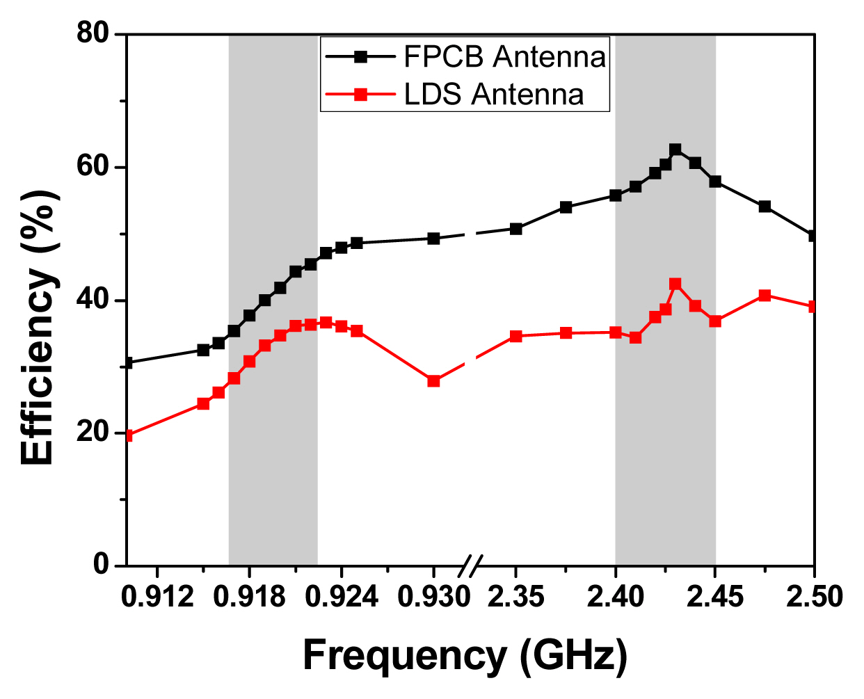
Comparison of the efficiency values of the F PCB and LDS antennas.
Additionally, the efficiencies of the FPCB antenna are better than 40% at UHFs and better than 55% at microwave frequencies. As depicted in Fig. 8, the efficiency of the FPCB antenna is greater than that of the LDS antenna. When comparing the LDS and FPCB technologies, FPCB is more convenient for impedance matching and adjusting the resonant frequency than LDS. As a result, the FPCB dual-band meander microstrip antenna was used for an RFID-based subway car maintenance system.
III. A Dual-Band Low-Power-Consumption Active RFID Tag
A dual-band low-power-consumption active RFID tag with a built-in wireless rechargeable battery was used in a subway car maintenance system. To reduce the power consumption of the tag and extend its battery life, two-stage wake-up circuits were preferred over continuous reception [12]. An incoming radio frequency signal of 900 MHz activates the 2.4 GHz part of the RFID tag. In this case, the current consumption is 6.289 mA to 15.087 mA at a voltage of 4.2 V. When there is no signal at 900 MHz, the active RFID tag goes into a wait-time state after 15 seconds. In this state, the current consumption is 3.4 μA at 4.2 V. Consequently, the estimated battery life is approximately 6 years when the average wait-time of the RFID tag is 86,295 s/day. Table 1 shows the specifications of the dual-band low-power-consumption active RFID tag developed for the subway vehicle maintenance system.
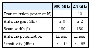
Specifications of the dual-band low-power-consumption active RFID tag
The antenna gain is more than 0 dBi at 900 MHz and more than 2 dBi at 2.4 GHz. The beam width is 180°, and the antenna polarization is linear. In addition, the sensitivity is better than −14 dBm at 900 MHz and better than −95 dBm at 2.4 GHz.
IV. Field Test
To verify the performance of the developed dual-band low-power-consumption active RFID tag, various field tests were carried out in the Seoul Metropolitan Subway in South Korea.
Fig. 9 shows the installation of the measuring equipment in a rail yard and a moving area. In the rail yard, the reader and reader antenna were installed under the ground equipment, while the tags were installed on the trains. In the moving area, the reader and reader antenna were installed on the subway trains, and the tags were installed on the ground. The readers used for the field measurements operated in dual bands. In the UHF band, the transmit power was 30 dBm and the antenna gain was 6 dBi. In the microwave band, the transmit power was 10 dBm and the antenna gain was 12 dBi. The proposed dual-band tags were used. The tag recognition distance can be calculated using Eq. (1).

Installation of the measurement equipment: (a) setup in a railway yard and (b) setup rate in moving area.
R1: Distance from transmitter to tag,
EIRPTX: Effective isotropic radiation power.
The variable RANGE represents the recognition range from the forward link to the tag. In fact, the recognition range of the tag requires a comprehensive analysis of the reverse link range, the direction and polarization of the tag, the impedance matching of the tag, and the direction and polarization of the reader antenna [13, 14].
First, the read range of the present RFID tag was measured at an inspection shed and at a subway train rail yard of Seoul Metropolitan Subway. In vehicular applications, RFID tags are generally mounted on the vehicle and the readers on the roadside unit [15]. For the field operational tests, the present RFID tags were attached to a main air compressor, a traction motor, and an air dryer, as illustrated in Fig. 10.
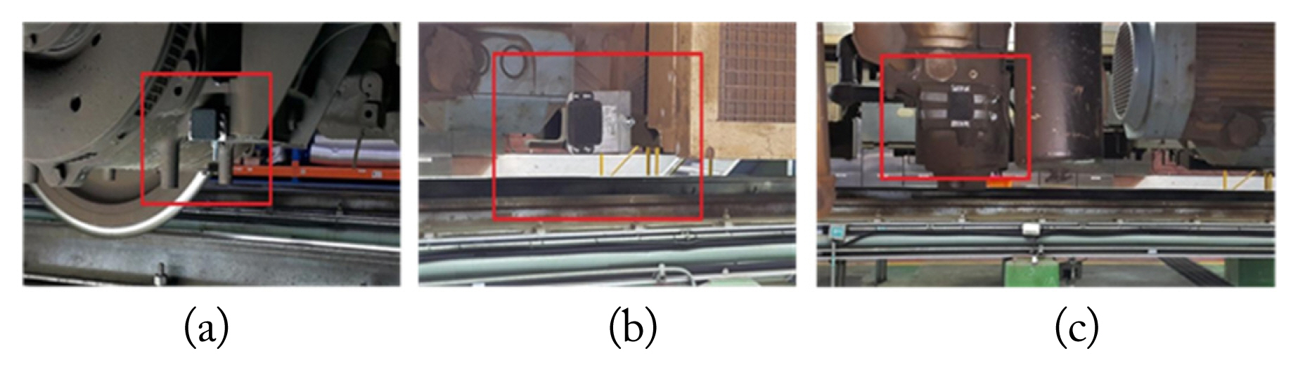
RFID tags mounted (a) on a main air compressor, (b) on a traction motor, and (c) on an air dryer.
After that, a subway train moved from the rail yard into the inspection shed at a speed of 5 km/h. Table 2 shows the read range values of the RFID tags measured using the Seoul Metropolitan Subway facilities and trains.

The read ranges measured using the present RFID tag in the Seoul Metropolitan Subway
Moreover, the measurements of the recognition rates of the present RFID tags were carried out at the inspection shed of Seoul Metropolitan Subway. For the field tests, the RFID readers were attached under the inspection track, while the RFID tags were mounted on 10 traction motors, 10 main air compressors, and 10 air dryers. In these circumstances, the recognition rate measurements of the RFID tags were registered over 40 days whenever the subway trains came into the inspection shed.
Table 3 illustrates the recognition rates of the RFID tags measured in the Seoul Metropolitan Subway. These are 100% in the case of 2.4 GHz, but only 95% and 98% at 900 MHz for the RFID tags mounted on traction motors and main air compressors, respectively. The recognition rate for the 900 MHz case was 100% when the tags were in the strong-in-field region, but it went down to as low as 95% in the weak-in-field region, where the tags are subjected to the effect of the metallic surface environments on which they are mounted. The relationship between electric vehicle speed and tag communication velocity is expressed by Eq. (2).
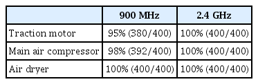
Recognition rates measured using the present RFID tag in the Seoul Metropolitan Subway
MV: Electric vehicle speed,
DRANGE: Communication distance of the reader antenna used,
TTAG_ACCESS: Tag access time (7,064 μs) at a communication velocity of 75 kbps.
From Eq. (2), when the RFID communication velocity is 75 kbps and the reader’s reading range distance is 1 m, the speed of the electric vehicle can reach up to 140 km/h. Additionally we experimented with how recognizable the RFID tag is for different orientations of the reader. The recognition rates of 30 tags located under subway trains with vehicle speeds up to 70 km/h were measured. For the first field test on orientation sensitivity, the RFID readers were placed in a line parallel to the subway track. The measurements were repeated 10 times to reduce measurement errors. In the second field test, the RFID readers were installed perpendicularly to the subway track to study the orientation sensitivity. Fig. 11 illustrates the recognition rates for different RFID reader orientations. As shown, the recognition rates were 100% when the RFID readers were placed in a line parallel to the subway track (horizontal polarization). On the other hand, the recognition rates were 99% when the RFID readers and the subway track were perpendicular (vertical polarization). Consequently, readers should be placed parallel to the tracks for optimal performance in subway car management systems. Subway cars constitute the most maintenance-intensive part of the subway system and are the most vulnerable if maintenance is neglected [16, 17].

Recognition rates in different RFID reader orientations.
V. Conclusion
Automated subway car maintenance systems using RFID technology are cost saving, time saving, reducing the possibility of human errors and bringing benefits to car knockers and passengers. The present RFID tag was designed to ensure the retrieval of information from an RFID tag located on subway cars with vehicle speeds up to 70 km/h and then transfer the uploaded information from the chip into the central information systems. The recognition rates were measured using Seoul Metropolitan Subway facilities and trains. In the strong-in-field region, the recognition rates of the proposed RFID tags were 100%. We did observe recognition rates as low as 95% in the weak-in-field region. In addition, field tests of the designed RFID tags using an automated subway car maintenance system were successfully performed. When a subway train moved from the subway rail yard into the inspection shed at a speed of 5 km/h, the average read ranges of the present RFID tags were 25 m at 900 MHz and 200 m at 2.4 GHz. It should be noted that the RFID readers need to be placed parallel with the subway tracks for optimal performance, according to our field test results. It is anticipated that accidents caused by mechanical failures on subway cars will be reduced though the subway car managing system based on the present RFID tag.
Acknowledgments
This work was supported by the technology development program funded by the Ministry of Trade, Industry & Energy, Republic of Korea (No. 10043982) and the Research Grant of Kwangwoon University in 2019.
References
Biography

Jung Hoon Cha received his B.S. degree in electronics engineering from Ulsan University, Korea in 1994, and his M.S. degree and Ph.D candidate in industrial engineering, Yonsei University, Korea in 2009 and 2013. He has been working CEO at COCONET Co., Ltd. His research interests include IoT Device/Network and 5G mobile communication for Cloud system.

Yong Jung Kim received his B.S. degree in broadcast video information from Dankook University, Korea in 2004. He is currently working towards his Ph.D. degree at the information display, Kwangwoon University. His research interests include 5G mobile communication for 3D hologram system.

Yong Cheon Cho received his B.S. and M.S. degrees in electronic materials engineering from Kwangwoon University, Korea in 1990 and 1992, respectively. He received his Ph.D. degree in information & communication engineering from Sejong University, Korea in 2019. Since 2014, he has been with the industry-academic collaboration foundation in Kwangwoon University, Korea, where he is currently a Professor. His research interests 5G mobile communication.

Hojun Lee received a Ph.D. in Radio Engineering from Kwangwoon University, Korea, in 2007. Since 2000, he has worked at Korea Electronics Technology Institute( KETI), where he is now a Chief Researcher at the Department of ICT Device & Packaging Research Center. His research interests include vehicle antenna.

Hak Yong Lee received his B.S. and M.S. and Ph.D. degrees in electronic wave (radio) engineering from Kwangwoon University, Korea in 1999 and 2001, 2005. he has been working CTO at MinongBio Co., Ltd. His research interests electro-bio system and IoT device and CITS and wide band antenna.