Free-Positioning Wireless Power Transfer Using a 3D Transmitting Coil for Portable Devices
Article information
Abstract
The free-positioning wireless power transfer (WPT) system has drawn attention in recent years. Traditionally, a WPT system can transfer energy in one or two directions on the same plane, but it leads the restrictions of angle and axis misalignment between a transmitter and a receiver coil. In this paper, we propose a free-positioning WPT system using a three-dimensional cubic-shaped transmitting coil for portable device charging. A small receiving coil is placed inside the transmitter to achieve the transferred energy through the magnetic resonant coupling. In addition, the equivalent circuit and the mutual inductance between the Tx and Rx coils are analyzed. Finally, a practical experiment is implemented to verify the transfer performance, which can reach up to about 50% power transfer efficiency. The proposed system can charge in spatial freedom.
I. Introduction
Wireless power transfer (WPT) has attracted much attention because of its potential application in consumer electronic products, portable devices, robotics, electric vehicles, and charging systems [1–6]. With the occurrence of portable device explosion, the demand for wireless charging is necessary to reduce the mass of the traditional wire charge system. The WPT system for portable devices has some restrictions. A conventional WPT system still suffers from efficiency degradation due to changes in the position of the receiver, such as the variations in the distance, angle, and axial misalignment. For convenient wireless charging and for overcoming the restrictions of the conventional WPT system, free positioning is necessary to create reliable wireless charging systems and maintain the power transfer efficiency (PTE). In recent research, the free-positioning WPT has been explored in comparison with the use of one direction or two directions on the same plane [7–9]. In [10], a WPT system using a bowl-shaped transmitting (Tx) coil for free-positioning is proposed for charging small electronic devices, such as hearing aids and wearable electronic devices with a rechargeable battery. However, the bowl-shaped coil presents a restriction when the small receiver (Rx) coil is in the perpendicular arrangement. Therefore, the mutual inductances between the Tx and Rx resonant coils are small, leading to a low performance of the system. Moreover, a resonant WPT system that allows the free-positioning of a wearable device at a 360° axis of rotation and the simultaneous charging of a mobile phone is proposed in [11]. The smartwatch is placed at a small fixed distance around the cylindrical charging surface. The application of this structure is quite specific and can charge a smartwatch and a mobile phone.
In [12, 13], a multi-directional magnetic resonant coupling WPT is presented using a cubic Tx design. A receiver (Rx) is placed outside of the Tx coil, and the spatial freedom of the Rx coil is not developed. In the current study, a WPT system with an Rx coil placed inside the cubic-shaped Tx coil is proposed for free-positioning. The WPT system is a two-coil WPT system that is compact and suitable for consumer applications compared with the four-coil WPT system, such as portable and wearable device chargers, mobile phones, and tablets. A circuit analysis of the proposed system is presented to obtain the maximum PTE. The system is simulated using Ansoft HFSS software and fabricated to evaluate performance.
This paper is organized as follows. The magnetic field of a Tx coil is evaluated and analyzed for free-positioning charging in Section II. The sceneries of the Rx positions inside the Tx coil are demonstrated to validate the spatial freedom charging. In Section III, the Tx and Rx coils are fabricated and measured to evaluate the efficiencies. The conclusion is presented in Section IV.
II. Free-Positioning WPT Analysis
In general, WPT through magnetic resonant coupling is experimentally demonstrated in a system with two resonant loop antennas in one or two directions on the same plane. A conventional WPT system suffers a misalignment between the Tx coil and the Rx coil on the planar charging platform. A coil designed with different geometries can modify the radiation pattern, which overcomes the inconvenience by increasing the direction of mutual coupling. A cubic-shaped Tx coil is proposed for free-positioning wireless charging with a small Rx coil that remains in spatial freedom. The purpose is to overcome the limitations of the conventional system.
1. WPT System with a 3D Transmitting Coil
Fig. 1 shows the Tx coil structure and the magnetic field vector generated by the driven current on each loop side of the cubic-shaped Tx coil [12]. The cubic Tx is constructed by folding the copper wire along the edges of the cube. The folding wire should be positioned in such a way that the current is driven as a closed-loop on each side of the cube, as shown in Fig. 1(a). In the first half of the period, the current follows counter-clockwise, resulting in the directions of the magnetic field to be perpendicular to each side of the cube and vice-versa using the right-hand screw rule, which is expressed as
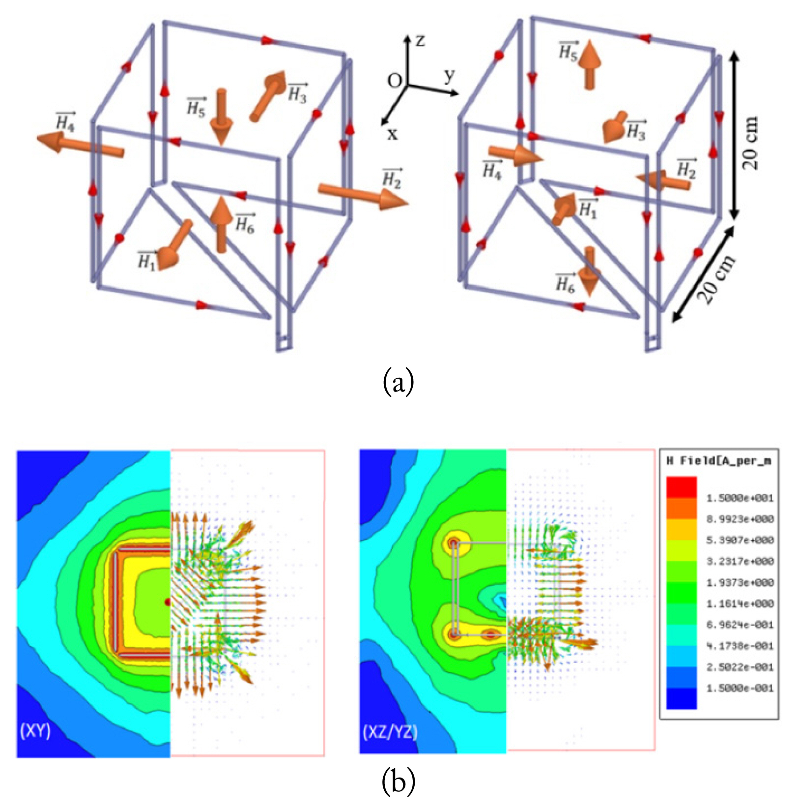
The cubic-shaped Tx coil structure: (a) magnetic field vector in each of the half-operating period T/2 and (b) magnetic field simulation with its magnetic field density and magnetic field vector.
2. Mutual Inductance Calculation
Fig. 2(a) shows the schematic diagram of the system for mutual inductance calculation, with the Rx position determined by the rotation angles ϕ and θ and the movement parameters dx, dy, and dz. To derive the mutual inductance between two coils, the Tx and Rx structures are divided into multiple pieces. Each Tx and Rx coil pieces are represented by a vector u⃗i(xi, yi, zi) and u⃗j(xj, yj, zj), respectively, and the vector direction is decided by the current direction in the corresponding coil. The transformation vector coordinates u⃗i(xi, yi, zi) and
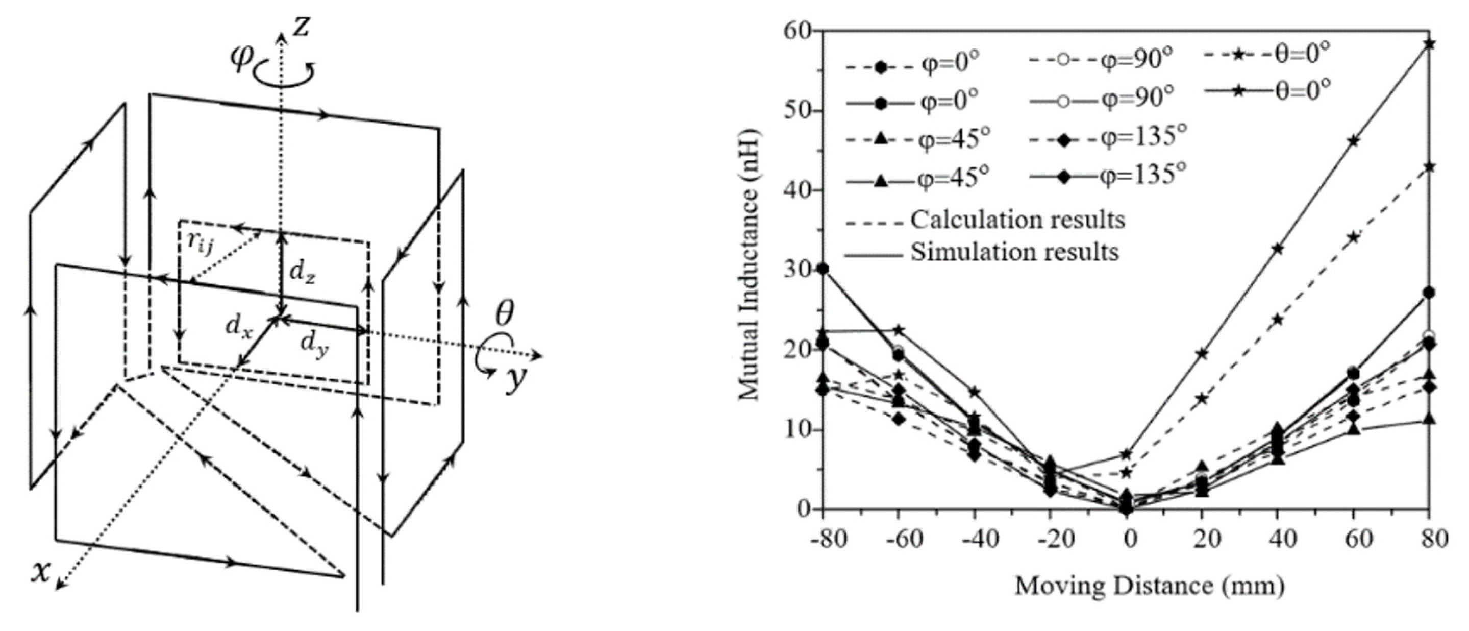
(a) Schematic diagram of the free-positioning WPT system; (b) calculated and simulated results of the mutual inductance between the Tx and Rx coils.
The overall mutual inductance between the Tx and Rx coils is obtained by the summation of the individual mutual inductances between two arbitrary coil pieces:
where N1 and N2 are the number of discrete segments in the Tx coil and Rx coil, respectively, and μ0 is the permeability of the free-space medium.
A comparison of mutual inductance between the calculated and simulated results is plotted in Fig. 2(b). There is a good agreement between the simulated and the calculated results obtained using (4). Owing to the cancellation of the magnetic field in the center region, the mutual inductances between the Tx and Rx coils are conducive to the low values in this area. The mutual inductances at the receiving angle θ are higher than the others because there are two diagonally folded wires at the bottom of the cubic Tx coil.
3. Circuit Model and System Analysis
Fig. 3(a) shows the sketch of the WPT system with the Rx coil placed inside the Tx structure. The volume of the Tx coil is 20 cm × 20 cm × 20 cm, and the dimension of the Rx coil is 10 cm × 10 cm. Both the Tx and Rx coils are made with copper wire with a diameter of 5 mm. Fig. 3(b) shows the equivalent circuit model of the proposed WPT system to analyze the transfer efficiency. The schematic is composed of two resonant circuits corresponding to the Tx and Rx coils. By using a series capacitor and a shunt capacitor, the coil impedance can be matched with almost all load impedances [13]. Kirchhoff’s voltage law (KVL) is used to determine the currents as presented by
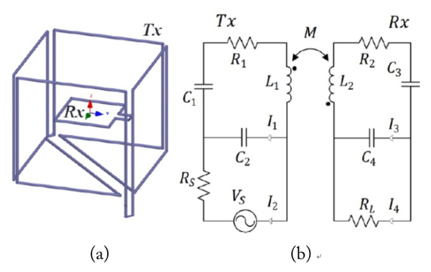
(a) Free-positioning WPT system in a 3D view. (b) Equivalent circuit model of the resonant coupling two-coil system, which is composed of lumped components.
where
The KVL equations are derived to explore the transfer function VL/VS:
The PTE is calculated according to the S21 by PTE = |S21|2 × 100(%). The equivalent |S21| scattering parameter can be calculated by
Fig. 4 illustrates the receiving positions of the Rx coil corresponding to the receiving angles ϕ, θ. With each receiving angle, the Rx coil is moved around the origin of the coordinate. By adjusting the Rx’s positions inside the space of the Tx coil, the PTEs of the system are verified, demonstrating the feasibility of the free-positioning wireless charging of the proposed system. The fabrication and experiment of the WPT system are presented in the following section.
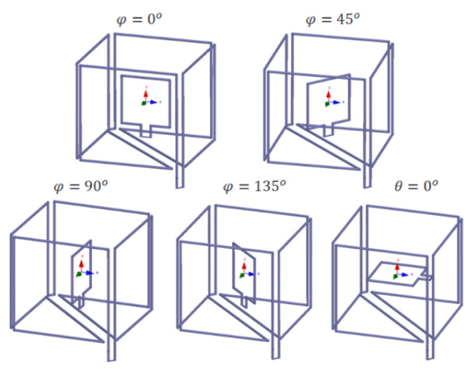
Cubic-shaped Tx coil structure with the Rx coil positions corresponding to the receiving angles ϕ, θ.
III. Fabrication and Experimental Validation of the WPT System
To verify the theoretical analysis, the resonant coupling system is constructed using a long copper wire with a radius of 2.5 mm for both the Tx and Rx coils. The total length of the copper wire for the cubic Tx coil is approximately 870 cm. The lengths of the edge sides of the Tx coil are the same at 20 cm. The real volume of the cubic Tx coil is 20.6 cm × 20.8 cm × 20.5 cm. The dimension of the Rx coil is 10 cm × 10 cm. To determine the working frequency, each coil is tested separately with a Protek A333 network analyzer (GS Instech, Incheon, Korea). The measured resonant frequencies of the Tx and Rx coils are 13.586 MHz and 13.574 MHz, respectively. The detailed values of the lumped elements and extracted parasitic components of the Tx and Rx coils are listed in Table 1. Fig. 5 illustrates the configuration of the free-positioning WPT system using a Protek A333 network analyzer.
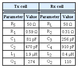
Extracted component values of the Tx and Rx coils
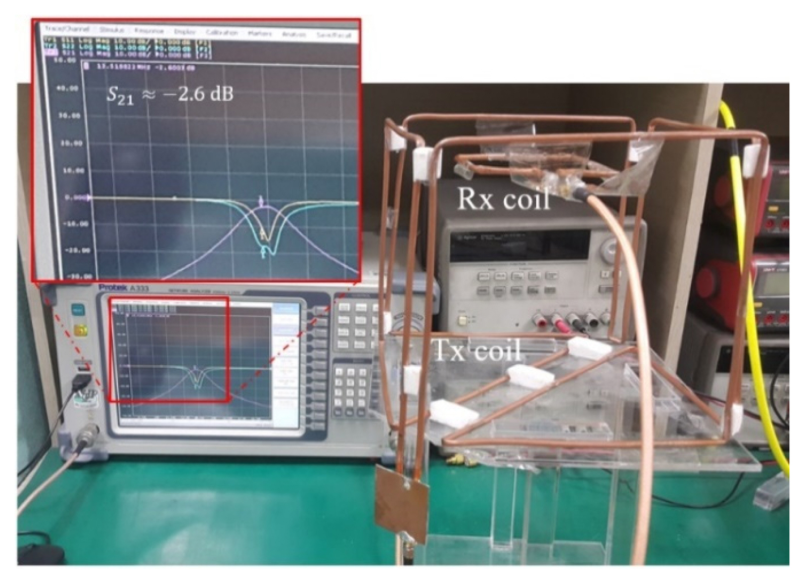
Measurement configuration of the resonant coupling system. Ports 1 and 2 of the Network Analyzer Protek A333 are connected to the Tx and Rx coils, respectively.
Once the Tx and Rx parameters and their working frequencies are established, the Rx coil is displaced up to 8 cm from the origin of the coordinate system inside the cubic Tx coil. Alternatively, the PTE of the WPT system can be measured as the ratio of the output power to the input power. A signal generator (Agilent E4436B; Agilent Technologies Inc., Santa Clara, CA, USA) is used to supply the input power to the Tx coil, and while a power meter is used to measure the delivered power of the Rx coil by a spectrum analyzer (Agilent 85665EC). The signal generator has a maximum generating power of 19 dBm. To extend the input power range, a +45-dBm drive amplifier is added to a transmitting module. The spectrum analyzer has a measured limitation of 30 dBm. Therefore, a −40-dB attenuator is used to reduce the power transferred to the spectrum analyzer. The experimental setup of the WPT system is shown in Fig. 6.
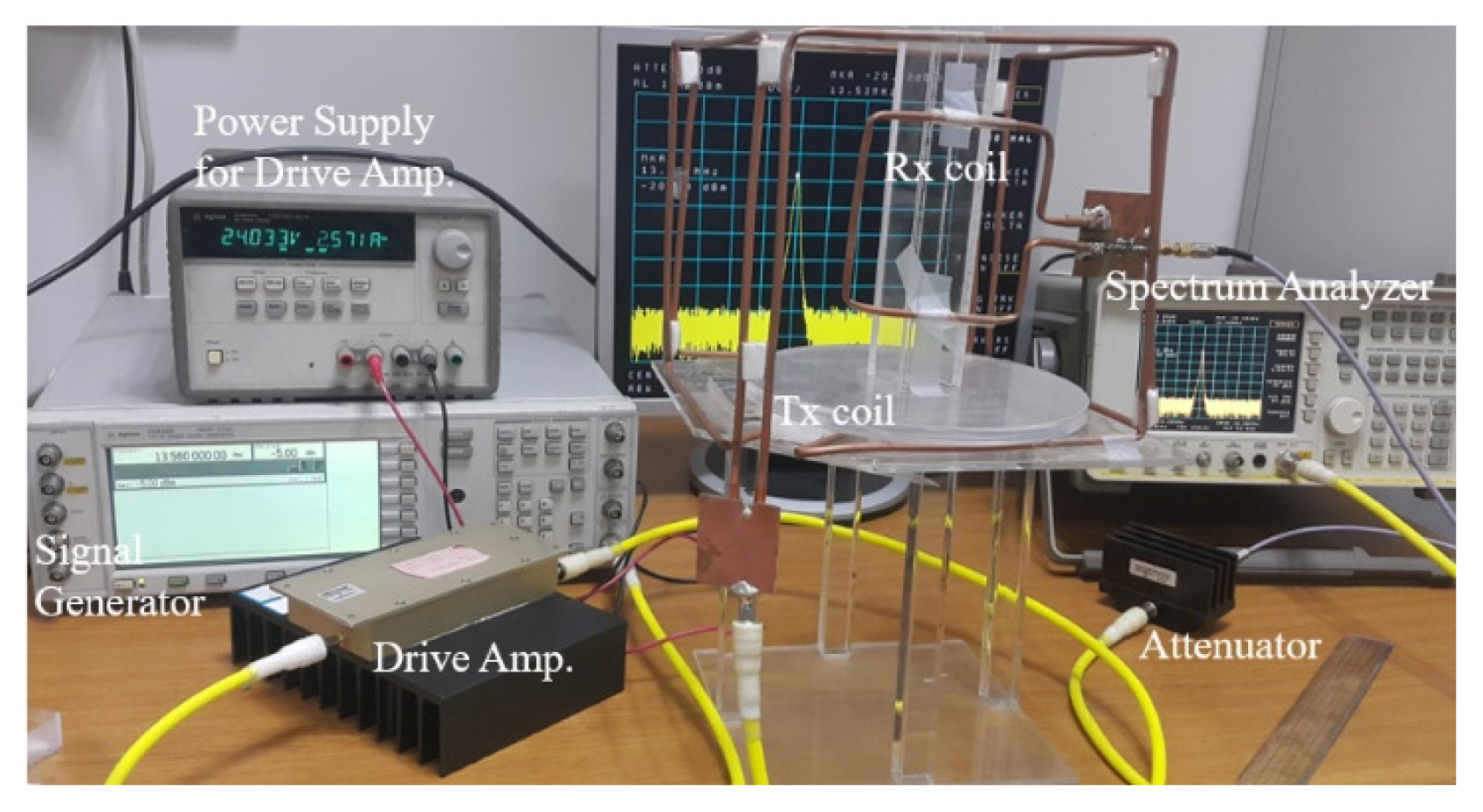
Experiment setup of the WPT system.
In this experiment, the generating Tx coil is maintained in a fixed position, and the Rx coil is arranged inside the Tx coil at various receiving angles. The PTEs of the WPT system are illustrated in Fig. 7.

Dependence between the PTE and the resonant coil distance. The distance is from the origin of the coordinate system to the Rx coil.
The Rx coil receives the highest energy at a distance of 4 cm from the origin of the coordinate system. In the small middle area of the Tx coil, the magnetic field is canceled because of symmetric construction.
Therefore, the PTEs are almost zero in the middle position leading to the dead zone of the Tx structure. However, the effective area inside the Tx coil is dominated in the small dead zone, which occupies over 62% of the spatial area. The Rx coil is freely placed in parallel and perpendicular arrangements. At effective distances, the PTEs can achieve 50%–60% at the operating frequency of 13.56 MHz at almost receiving angles. Table 2 shows a comparison of the structure types, system characteristics, possible arrangement, and performance of this study with those of previous research. Almost structures present some restrictions for wireless charging, such as dead zone existence, limited arrangement, and incomplete spatial freedom charging. The proposed cubic Tx coil still contains a small dead zone in the central region inside the structure. However, the Tx coil presents a compatible high PTE for the free-positioning WPT system, with the free placement of the Rx coil in parallel and perpendicular arrangements except for the narrow dead zone.
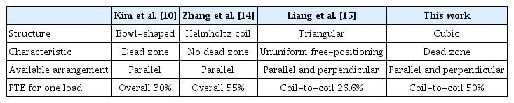
Comparison of the proposed system with those of related works
IV. Conclusion
We presented a cubic Tx coil design for the free-positioning magnetic resonant coupling WPT system. The proposed Tx coil could deliver power to the Rx coil arranged inside it with an efficiency of 50% at an operating frequency of 13.56 MHz and an optimum distance of 4 cm. The dependence between PTE and distance was investigated to validate the performance of the WPT system. In conclusion, low-cost fabrication without the current control methodology was implemented to verify the practical design of a cubic Tx coil with a simple single Rx coil.
Acknowledgments
This work was supported by the National Research Foundation of Korea (NRF) grant funded by the Korean government (MSIP) (No. NRF-2017R1A5A1015596) and by the Ministry of Education and Training (Project No. B2020-BKA-11).
References
Biography

Nam Ha-Van received his B.S. degree from the School of Electronics and Telecommunications, Hanoi University of Science and Technology, Hanoi, Vietnam, in 2012, and his Ph.D. degree in information and telecommunication engineering from Soongsil University, Seoul, South Korea, in 2019, where he is currently a postdoctoral researcher at the Soongsil University Foundation of University Industry Cooperation. His current research interests include wireless power transfer, metamaterials, power amplifiers, phased array antennas, and energy harvesting systems.

Hoang Le-Huu received his B.S. degree from the School of Electronics and Telecommunication, Hanoi University of Science and Technology, Hanoi, Vietnam, in 2018. He is currently pursuing his Ph.D. degree in information and telecommunication engineering at Soongsil University, Seoul, South Korea. His current research interests include wireless power transfer, antenna design, and computational electromagnetics.

Minh Thuy Le received he B.S. and M.S. degrees in electrical engineering from Hanoi University of Science and Technology, Hanoi, Vietnam, in 2006 and 2008, respectively, and her Ph.D. degree in optical and radio frequency from Grenoble Institute of Technology, France, in 2013. She is a lecturer and group leader of the radio frequency group at the Department of Instrumentation and Industrial Informatic (3I), School of Electrical Engineering, Hanoi University of Science and Technology. Her research interests include indoor localization, antenna, metamaterials, RF energy harvesting, and wireless power transfer.

Kwangsuk Park received his B.S. and Ph.D. degrees from the Department of Electronics Engineering in Seoul National University, Korea, in 1980 and 1985, respectively. He is currently a professor at the Department of Biomedical Engineering at Seoul National University and has been since he joined the department in 1985 as a founding staff member. He is a member of the Korean Society of Medical and Biological Engineering and has served as the president in 2014. He also served as the secretary general of the World Congress on Medical Physic and Biomedical Engineering held in Seoul in 2006. He is a senior member of IEEE EMBS and served as an associate editor of IEEE Journal of Biomedical and Health Informatics from 2006 to 2012. He served as the conference chair in EMBC2017. He has chaired and co-chaired the annual International Conference on u-Healthcare in the last 14 years. His main research area is biological signal measurement and processing for diagnosis. Currently, he is focusing his research interest on nonintrusive measurements for ubiquitous healthcare.

Chulhun Seo received his B.S., M.S., and Ph.D. degrees from Seoul National University, Seoul, South Korea, in 1983, 1985, and 1993, respectively. From 1993 to 1995, he worked at the Massachusetts Institute of Technology, Cambridge, MA, USA, as a technical staff member. From 1993 to 1997, he worked as an assistant professor at Soongsil University, Seoul, Korea. From 1999 to 2001, he was a visiting professor at MIT. From 1997 to 2004, he served as an assistant professor at Soongsil University, where he has been a professor of electronic engineering since 2004. He served as the IEEE MTT Korea Chapter Chairman, from 2011 to 2014. He is the Director of the Wireless Power Transfer Research Center supported by the Korean Ministry of Trade, Industry, and Energy, and the Director of Metamaterials Research Center, which is supported by the Basic Research Laboratories through the NRF Grant funded by the MSIP. His research interests include wireless communication technologies, RF power amplifiers, and wireless power transfer using metamaterials.