Panel Misalignment Effects on the Radiation Pattern from a Solid Surface Deployable Antenna
Article information
Abstract
This paper presents an analysis of antenna performance degradation due to the panel misalignment in a solid surface deployable antenna. The misalignment of the panel causes a phase error at the aperture plane due to path length differences. The radiated field is rapidly calculated using the aperture phase error method with analytic integrations in the case of uniform panel misalignment and quarter-zone uniform misalignment. The effects of the panel misalignment on the co-polarization characteristics of gain and side-lobe level (SLL) are calculated. Beam tilting is observed when the panel misalignment occurs uniformly in the half-zone of the whole panel area.
I. Introduction
Reflector antennas in satellites are used in applications such as data transmission and remote sensing because they have the advantage of having more than 30 dB of gain and a broad bandwidth [1, 2]. Recently, deployable antennas, which are folded in order to be carried with reduced volume in the launch vehicle and deployed in space, have been widely employed in satellites to accomplish large diameter antennas [3]. A solid surface deployable antenna provides lower surface errors than mesh or inflatable antennas, and it can be operated in a high-frequency range.
Solid surface deployable antennas are composed of a central dish and deployable panels. The panels are linked at the rim of the central dish, and they are folded during launch and deployed in space [1, 4]. The solid antennas can be lightweight using composite materials such as carbon fiber-reinforced plastic for the panels and the central dish [5, 6]. An imperfect deployment, which causes the misalignment of deployed panels, is possible in the process of deployment in space. Therefore, analyzing the effect of the misalignment on the performance of the antenna is necessary.
Depending on the type of malfunction of deployment devices, the misalignment of the panels shows different configurations. When the deployment is incomplete, the panels misalign uniformly. Moreover, the panels in some area can be assumed to be uniformly misaligned to provide a tilted radiation direction from the antenna axis.
The aperture phase error (APE) method calculates the radiated field of the reflector antennas by accounting for the phase errors in the aperture plane caused by the surface errors of the reflector [7, 8]. The APE method is effective in the case of uniform misalignment as the analytic integration in the angular direction may obtain the radiation pattern. The integration by Gaussian quadrature in the radial direction gives rise to more reduced calculation time. Furthermore, an analytic integration of the aperture field for the case of a partial misalignment may provide fast calculation results to determine the effects of asymmetric misalignments.
In this paper, the degradation effects on the co-polarization characteristics from the uniform panel misalignment error is analyzed using the APE method. Fast calculation is performed using analytic integration in the angular direction and the Gaussian quadrature in the radial direction. The whole panel area is divided into four zones, and an analytic integration is provided by the use of an integral formula when the panel misalignment is uniform in the quarter zones.
II. APE Method for Fast Calculation
Fig. 1(a) illustrates the configuration of the solid surface deployable antenna with a uniform panel misalignment error, and this antenna is compared with the completely deployed ideal parabola antenna. It is assumed that the central dish has no errors and that the misalignment errors exist in the panel area. Fig. 1(b) describes the geometry of the panel misalignment. The diameter of the reflector antenna is D and that of the central dish is d. The angle error of the panel misalignment is α degrees, and the surface error is ɛ meters. If the feeder is located at the focal point of the parabola, the phase of the reflected wave is uniform at the aperture plane, as the path length in traveling from the focal point to the reflector surface and to the aperture plane is constant for any point in the aperture. The panel misalignment results in the surface error ɛ, which results in the phase error at the aperture plane.

(a) Uniform misaligned panels and the ideal antenna. (b) Geometry of the panel misalignment.
The phase error at the aperture plane is obtained from the difference in the path length due to the surface error as illustrated in detail in Fig. 2. As the angle error of the panel misalignment is small, the rays reflected from the ideal parabola and the misaligned reflector are assumed to be parallel. The surface error due to the panel misalignment is obtained from Fig. 1(b) as
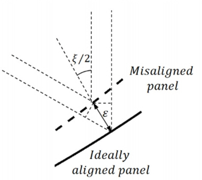
Difference in the path length due to the panel misalignment.
The phase errors in the aperture plane give rise to the change in the radiation pattern and degrade the performance of the antenna.
The radiation pattern in the far-field region is calculated from the field distribution of the circular aperture. The amplitude of the aperture field is assumed to be expressed as
where C(≤1) is the edge illumination relative to that of the center [2]. P has the value between 1 and 2 and is determined by comparing the aperture distributions from (2) and the radiation pattern of the feed horn. In our calculation, C is assumed to be 0.25, which corresponds to the edge tapering of −12 dB and P = 2.
1. Uniform Panel Misalignment
For the uniformly misaligned panels, the radiated pattern is obtained from the distributions of amplitude and phase of the aperture field. The phase error in (1) and the amplitude distribution in (2) are used in the equation. As the misalignment error occurs only in the area of the panels, the integration is divided into two sections of the central dish and the panels. The pattern factor of the radiated field in the far-field region is
Here, the phase error δ changes only in the radial direction (ρ̂) but does not change in φ̂ because the misalignment is uniform for every panel. Performing the integration in φ̂ using a closed-form solution [2], the resulting expression in the radiated field becomes
The radiated field pattern is calculated from (4) for the frequency of 9.6 GHz, and the feed system is located at the focal length of 1.1 m. The diameter of the antenna is assumed to be 3 m and that of the central dish 0.8 m. In the calculation of the aperture field, the APE method takes into account of the phase errors due to the panel misalignment. The accuracy of the APE calculation is hampered when the panel misalignment angle exceeds the limit because of the direction change of the ray reflected from the misaligned panel. In Fig. 3, the pattern calculated by the APE method is compared with the GRASP program in the case of α = 0°, 0.5°, and 0.8°. The number of panels is 30 in the GRASP simulation. The calculation by the APE method has been verified to provide reasonable results. In our calculation, the angle error α is limited to be less than the maximum angle error of 0.5°.
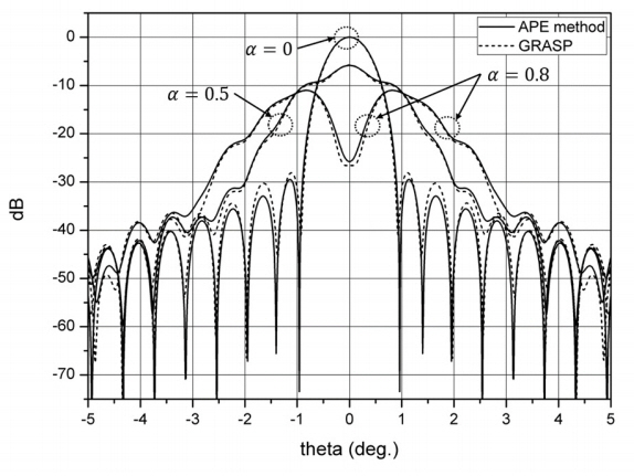
Comparison of the radiation pattern by the APE method with an electric field pattern by the GRASP simulation.
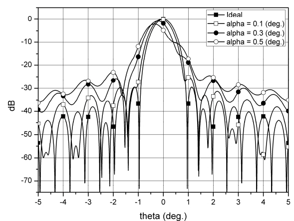
Fig. 4 shows the degradation of the radiation pattern from the solid deployable antenna when the panel misalignment is uniform and α increases from 0° to 0.5°. For the uniform misalignment, the direction of the main lobe is preserved to be aligned with the antenna axis as the error is symmetric in the φ–direction. The beam width grows and the SLL increases with the increase in α . The first side lobe is merged into the main lobe for α = 0.1°, 0.2°, and 0.3°, and the first and second side lobes are merged for 0.4° and 0.5°.

Radiation patterns for panels with uniform misalignment errors.
Calculating the radiation pattern for the panel misalignment takes less than 0.25 seconds when the APE method is used with MATLAB. An Intel Core i7-2600 K CPU with RAM of 32.0 GB is used. Table 1 summarizes the effects of the uniform misalignment on the performance of the antenna. As the phase error in the aperture plane monotonically changes along the ρ̂ direction because of the panel misalignment, the collimation of the rays is not perfect. The calculated radiation pattern shows the increase in the beam width by the panel misalignment, and the gain decreases. The loss of the gain is 5.86 dB for an angle error of 0.5°.
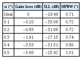
Degradation of antenna performance for uniform misalignment errors
2. Uniform Misalignment in the Quarter Zones
It is of interest how the radiation pattern is affected when the misalignment error is not uniform in all panels and panel misalignment occurs in some panels. For the sake of the analysis of the radiation pattern for the partially uniform misalignment, the panel area is divided into four quarters as illustrated in Fig. 5(a). The misalignment angle error is assumed to be uniform in the quarter area, and it may be given differently for different quarters. In this case, the solution for the radiation pattern is obtained analytically. Fig. 5(b) shows the configuration of the panels when the misalignment uniformly occurs in the first and fourth quarters.

(a) Area of the panels divided into four quarter zones. (b) Uniformly misaligned panels in the first and fourth quarter zones.
To obtain the radiation pattern, the integral for the panel area is divided into four integrals corresponding to each quarter by assuming that the angle error is differently given for each quarter as follows:
Here, δi (ρ̂) represents the surface error due to the angle error corresponding to the ith quarter. The analytic solution of the integrals in (5) is obtained in φ̂ using [9]
where I0 and L0 are the modified Bessel and the modified Struve functions, respectively. (6) is verified by comparing the numerical calculations of the integrals with the results from the formula on the right-hand side. The resulting expression for the radiated field is obtained for φ as
where
and ψ = kρ̂ sin θ . The radiation pattern is obtained for the observation points at
To determine the effects of the asymmetric deployment, the radiation patterns are calculated when half of the panels are misaligned and the other half is completely deployed. In Fig. 6, the radiation pattern at the φ= 0° plane is shown when the misalignment errors are uniform for the panels in the first and fourth quarter zones with angle errors of 0°–0.5°. The main lobe is tilted to the opposite direction from the side of the misaligned panel because of the geometry of the misalignment. The SLL is higher on the opposite side of the incompletely deployed panels. The first side lobe is merged into the main lobe for α = 0.3° and 0.5°, and the corresponding beam widths slightly increases.
Radiation patterns at the φ = 0° plane for uniformly misaligned panels in the first and fourth quarter zones.
The calculation time for each radiation pattern in the case of misalignment in the quarter zones is less than 1.6 seconds. The summarized effects of the uniform misalignment in the first and fourth quarter zones are presented in Table 2. The tilting angle of the main lobe increases to 0.35° to the opposite side for a maximum misalignment error of 0.5°. Moreover, the gain degradation increases from 0.09 dB to 2.09 dB for the increase in angle error from 0.1° to 0.5°.
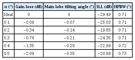
Degradation of antenna performance for uniform misalignment errors in the first and fourth quarters
III. Conclusion
The radiation pattern from a solid deployable antenna is analyzed when panel misalignment exists because of incomplete deployment. The effects are simply calculated from the APEs caused by a uniform misalignment error and a quarter-section misalignment error. The analytic solution of the integral enhances the calculation time for the radiated field and provides cross-validation by comparing the results with a commercial program. Moreover, analyzing the effects of misalignment for changes in the angle error is more convenient, and identifying the physical meanings is easier. Research on antenna performance may present a criterion on the misalignment error bound for the sake of having an acceptable operation of the antenna because of the incomplete deployment.
Acknowledgments
This work was supported by Global Surveillance Research Center (GSRC) program funded by the Defense Acquisition Program Administration (DAPA) and Agency for Defense Development (ADD).
The authors would like to thank W. B. Kim and S. H. Lee from the Korea Aerospace University for their assistance in calculating the effects of the quarter-zone misalignments.
References
Biography

Seung-Joo Jo received her B.S. degree in electronics and information engineering from Korea Aerospace University, Goyang, Korea, in 2018. She is currently working toward her M.S. degree at the Microwave and Radar Lab of Korea Aerospace University. Her research interests include satellite communication antenna, antenna design, and analysis.

Taek-Kyung Lee received his B.S. degree in electronic engineering from Korea University, Seoul, Korea, in 1983, and his M.S. and Ph.D. degrees in electrical engineering from the Korea Advanced Institute of Science and Technology (KAIST), Daejeon, Korea, in 1985 and 1990, respectively. From 1990 to 1991, he was a post-doctoral fellow at the University of Texas at Austin, Austin, TX, USA, under a grant from the Korea Science and Engineering Foundation. From 1991 to 1992, he was a research scientist at KAIST. In 1992, he joined the faculty of Korea Aerospace University (KAU), Goyang, Korea. He was an associate visiting research professor at the University of Illinois at Urbana–Champaign, Champaign, IL, USA, from 2001 to 2002. From 2006 to 2007, he was the chairman of the School of Electronics, Information, and Computer Engineering at KAU, where he was the director of the Aerospace and Aviation Electronics Research Center, from 2011 to 2013. He was the Chairman of the Radar Technical Group, Korean Institute of Electromagnetic Engineering and Science, Seoul, from 2012 to 2013, and he served as the president of this institute in 2014. He is currently a professor at the School of Electronics and Information Engineering, KAU. His current research interests include computational electromagnetics, antennas, microwave passive circuits, satellite antennas and spaceborne SAR system, and air surveillance system.

Ji-Yong Lee received his B.S. and M.S. degrees in electronics and telecommunications from Korea Aerospace University, Goyang, Korea, in 2014 and 2016, respectively. He is currently working at the Agency for Defense Development. His research interests include antennas, radar, and microwave.

Seong-Sik Yoon received his B.S., M.S., and Ph.D. degrees in electronic engineering from Korea Aerospace University, Goyang, South Korea, in 2010, 2013, and 2018, respectively. He is currently senior researcher at Laboratory of Radar PGM in Hanwha Systems. His current research interests include satellite communication antenna, radar antenna design and analysis, and spaceborne SAR system.

Jae Wook Lee received his B.S. degree in electronic engineering from Hanyang University, Seoul, Korea, in 1992, and his M.S. and Ph.D. degrees in electrical engineering with a specialization in electromagnetics from the Korea Advanced Institute of Science and Technology, Daejeon, Korea, in 1994 and 1998, respectively. From 1998 to 2004, he was a senior member of the Advanced Radio Technology Department, Radio and Broadcasting Research Laboratory, Electronics and Telecommunications Research Institute, Daejeon. He was with the faculty of Korea Aerospace University (KAU), Goyang, Korea. He is currently a professor at the School of Electronics and Information Engineering of KAU. His current research interests include high-power amplifier design, computational electromagnetics, electromagnetic interference/electromagnetic compatibility analysis on printed circuit boards, and satellite antennas and spaceborne SAR system.