A Compact Rx Antenna Integration for 3D Direction-Finding Passive Radar
Article information
Abstract
A compact receiving (Rx) antenna integration for 3D direction-finding passive radar is proposed. The proposed antenna integration consists of two Yagi antennas and two waveguide slot antennas. The antennas are mounted on four sides of a parallelepiped polycarbonate module with the same type of antennas facing each other on the opposite sides of the module. The antenna is designed for a direction-finding radar system as an Rx terminal on an avionic vehicle with a separate Tx base station on the ground. The proposed antenna integration demonstrates a maximum return loss of 9.6 dB (voltage standing wave ratio 2:1) ranging from 9.7 to 10.2 GHz in the X band and has suitable radiation patterns for direction-finding system in both the xz and yz planes. In addition, the proposed antenna integration has the compact size and light gross weight of 37 mm × 46 mm × 50 mm and 97 g, respectively, making it suitable for application in an avionic system.
I. Introduction
With the rapid development of commercial and military avionic radar systems, interest in antenna design technology for guidance and control systems for avionic vehicles has increased explosively during the past few years. To meet the performance requirements of the antennas mounted on an object for direction-finding, many studies have been conducted [1–6]. To reduce power consumption, the antenna usually operates in passive Rx mode, with an additional Tx base station on the ground [7], as shown in Fig. 1. The Tx station first transmits a signal to the target in the air. When the reflected signal from the target hits the Rx antenna, the front-end receiver module deduces the amplitude of it as DC voltage [8, 9]. After processing and computing that voltage value, the direction of the incoming signal can be found by analyzing the differential amplitude of the voltage measured from each Rx channel. Thus in the industrial field, multi-channel Rx antenna integrations are generally used [10]. Each antenna is mounted on four faces of a parallelepiped antenna module on an avionic vehicle as shown in Fig. 2. When using the amplitude comparison scheme for direction-finding, ambiguity of the gain amplitude can become an issue that affects the accuracy of the system [11]. To eliminate that ambiguity in a four-channel direction-finding system, the radiation patterns of the four antennas in Fig. 2 should be similar to the patterns shown in Fig. 3 [12]. In the ideal of that case, the gain difference between ANT1–ANT2 and ANT3–ANT4 in xz and yz planes can be graphically deduced as the plots given in Fig. 4. To satisfy all those properties, we here propose a compact and light-weight Rx antenna integration suitable for a 3D direction-finding radar system.
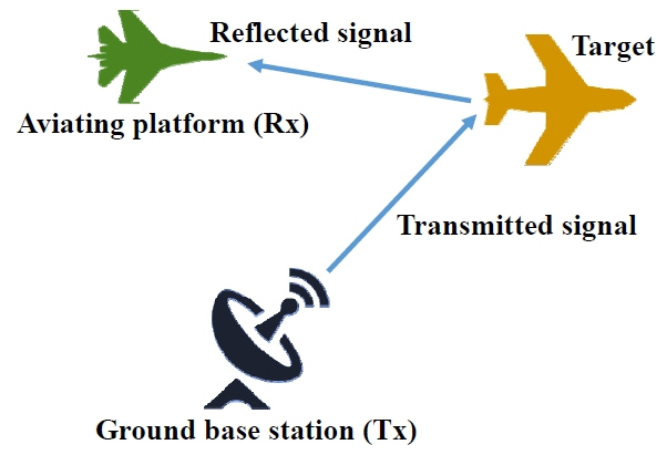
Operating principal of the application.

Four antennas mounted on a paralleled piped module for direction-finding application: (a) perspective view and (b) front view.

A brief example of ideally suitable radiation patterns on xz plane (a) and yz plane (b).

A brief example of ideal gain difference between ANT1–ANT2 and ANT3–ANT4 in (a) xz plane (b) yz plane.
II. Design of Single Antenna Elements
With reference to the radiation patterns in Fig. 3, four antennas need to be chosen to generate the required beam patterns. However, because the Tx antenna of a ground base station system usually has a sharp beam with linear polarization [13, 14] (e.g., dipole or patch array), the linearly polarized planes of the four Rx antennas must coincide with one another to receive the reflected signal from the target. One way to obtain that property is to use four identical antennas, such as a dipole antenna on each side of the platform, as shown in Fig. 5(a). However, that configuration requires a significant amount of space for the antennas. Therefore, we propose two Yagi antennas and two waveguide slot antennas for ANT1–ANT2 and ANT3–ANT4 in Fig. 2, respectively, as shown in Fig. 5(b), which requires much less space.

Comparison of space occupancy between two types of antenna integration using (a) four identical antennas and (b) two types of antenna pairs with polarization orthogonal to each other.
1. Microstrip Yagi Antenna
The single element for a microstrip Yagi antenna is illustrated in Fig. 6. The antenna consists of an SMA connector, dipole element, rear reflector, front driver, polycarbonate (PC) spacer, bottom reflector, and two PC bolt screws. Parameters of the antenna were calculated using the basic properties of a general Yagi antenna [15], as shown in Table 1, and then fine-tuning them using HFSS software (version 2016.2, Ansys Corporation, Pittsburgh, PA, USA). The simulated return loss of the antenna is shown in Fig. 7. The bandwidth of the antenna to achieve voltage standing wave ratio (VSWR) 2:1 is 9.25–11.8 GHz. As a conventional Yagi antenna, the antenna has a directive and nearly symmetric radiation pattern in the xz plane [16], as shown in Fig. 8. On the other hand, the antenna exhibits a tilted beam from the +z to +y direction at 50°, as shown in Fig. 8, due to the bottom reflector made of FR4 substrate with a full metal pattern on its upper side. In addition, the antenna is linearly polarized in the xz-plane according to the nature of a dipole antenna [17].
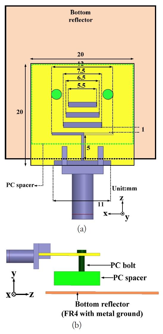
Geometry of the proposed Yagi antenna element: (a) top view and (b) side view.

Theoretical values for parameter of Yagi antenna
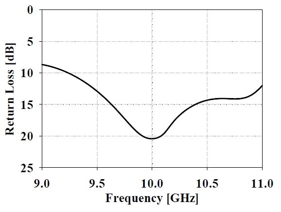
Simulated return loss of the Yagi antenna element.

Simulated radiation pattern of the Yagi antenna element at 10 GHz with and without bottom reflector.
2. Waveguide Slot Antenna
The single element of a waveguide slot antenna is designed as shown in Fig. 9. The resonant frequency is determined by the half-wavelength (λ/2) central slot on the top of the waveguide. Impedance matching was achieved by placing a conducting metal block inside the waveguide and adjusting the gap between the feeder pin and the block. The simulated result shows that the bandwidth of the antenna to achieve VSWR 2:1 is 9.85–10.23 GHz, as shown in Fig. 10. Unlike conventional waveguide slot antennas [18–20], the waveguide slot antenna in this paper has three corrugation grooves on the top wall of the waveguide. The one in the rear is for suppressing the surface wave toward −z direction, and the two in the front induce more surface wave toward the +z direction. The former is placed λ/2 away from the slot and the latter are located close to the slot to obtain the tilted main beam [21–23]. Fig. 11 illustrates the effect of each corrugation on the main beam direction of the antenna in the xz plane. As a final optimized result, the main beam of the waveguide slot antenna in the xz plane is tilted 45° from the +x direction to the +z direction while being symmetric in the yz plane, as shown in Fig. 12. In addition, the antenna is linearly polarized in the xz plane according to the nature of a waveguide slot antenna [17].

Geometry of the proposed waveguide slot antenna element: (a) top view and (b) cross-sectional side view.
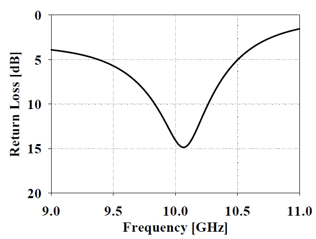
Simulated return loss of the waveguide slot antenna element.

The effect of corrugation grooves on the radiation pattern of the antenna in xz plane.

Simulated radiation pattern of the waveguide slot antenna element in both xz and yz planes at 10 GHz.
III. Antenna Integration Design
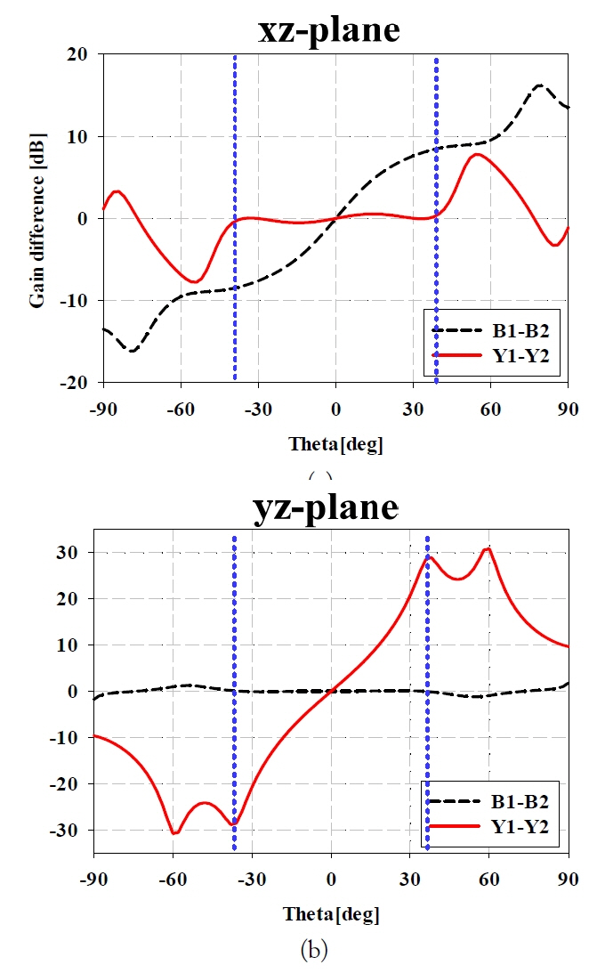
As illustrated in the previous section, the antenna integration consists of two Yagi antennas (Y1 and Y2) and two waveguide slot antennas (B1 and B2) mounted on each side of the plastic module, as shown in Fig. 13. Considering the position of the mounted antennas, the linearly polarized plane of the four antennas is identical (i.e., coincides with the xz plane) due to the polarization characteristics of the antenna types. The module for mounting the integrated antennas is made of PC (ɛ r = 2.8), which is economical, easily machinable, and lightweight. The simulated return loss characteristics of the antenna mounted on the module are shown in Fig. 14. All four antennas satisfy the maximum return loss level of 9.6 dB (i.e., VSWR 2:1) from 9.85 GHz to 10.15 GHz. Fig. 15 briefly illustrates the E-field distributions of both antennas mounted on the module to verify the origination of the tilted main beams in both the xz and yz planes. Compared with the proposed Yagi antenna in the yz plane, the waveguide slot antenna has a broader radiation pattern in the xz plane due to the nature of the antenna mechanism. Therefore, to obtain a steeper gradient—i.e., larger value of (dBi/theta degree)—for the gain plot in the xz plane, both waveguide slot antennas are rotated about 3° toward the z-axis, which makes the radiation pattern similar to that in Fig. 3. As shown in Fig. 16, the gradient of the gain decrement versus theta becomes steeper in general as the antenna is rotated but starts to flatten from 4°. Fig. 17 illustrates the optimized result for simulated radiation patterns of the proposed antenna integration at 10 GHz in the xz and yz planes. As shown in the figure, the radiation patterns of the B1 and B2 are identical in the yz plane and symmetric in the xz plane. On the other hand, the radiation patterns of Y1 and Y2 are identical in the xz plane and symmetric in the yz plane. In addition, the maximum gains of the B-type antennas in xz plane and the Y-type antennas in yz plane are 7.5 dBi and 8.1 dBi, respectively.
Geometry of the proposed antenna integration: (a) perspective view and (b) rear view.

Simulated return loss of the proposed antennas.

E-field distributions of two antenna types at 10 GHz: (a) waveguide slot antenna in xz plane and (b) Yagi antenna in yz plane.

Effect of the rotation of the waveguide slot antenna on the gradient of the gain versus theta in xz plane.

Simulated radiation patterns of the proposed antenna at 10 GHz: (a) xz plane and (b) yz plane.
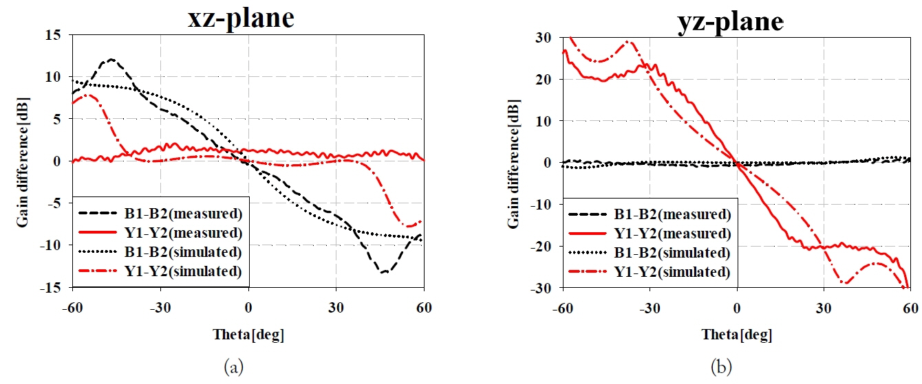
To analyze the suitability of the radiation pattern illustrated in Fig. 3, we conducted a graphical manipulation. The plots in Fig. 18 indicate the gain difference between the antennas with identical types in the xz and yz planes at 10 GHz. The gradient of the gain difference plots between B1 and B2 in the xz plane and Y1 and Y2 in the yz plane are steep, whereas that between B1 and B2 in the yz plane and Y1 and Y2 in the xz plane are relatively flat. Thus, the antenna integration generally satisfies the property explained in Fig. 4. However, there is a certain range within which its performance deteriorates (e.g., |theta| >40° in both the xz and yz plane). Outside that range, the radiation patterns of the proposed antenna integration offer good performance for direction-finding application. On the other hand, the slope of gain differences of Y1 and Y2 in the yz plane and B1 and B2 in the yz plane are not identical to each other. However, this can be overcame by employing calibration factor to the gain difference slope at the signal processing stage in order to eliminate possible error of the direction finding system.
Gain difference between B1–B2 and Y1–Y2 at 10 GHz vs. theta: (a) xz plane and (b) yz plane.
IV. Experimental Results
1. Fabrication of the Proposed Antenna
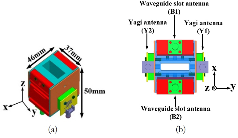
Because the proposed antenna integration combines four antennas onto a plastic assemblage module, three mechanical processing techniques were used to fabricate the whole structure. First, computer numerical control (CNC) machining was used to manufacture the PC module and spacer. PC was used because it is inexpensive, easily machinable, and has a relatively high tolerance to heat and impact [24]. Second, an etching process was used to fabricate the Yagi antenna and FR4 reflector. For the waveguide slot antennas, electroforming was applied because the bent inner space is difficult to realize using CNC machining [25]. To minimize unexpected degradations in performance, all the bolts used to fasten the subparts were made of PC. Fig. 19 illustrates the finalized antenna integration. The total dimensions of the proposed antenna integration are 37 mm × 46 mm × 50 mm and its gross weight is 97 g. Therefore, the proposed antenna integration is both compact and light, which are great features for being mounted onto an avionic vehicle system.

Fabricated antenna integration: (a) perspective view and (b) rear view.
2. Measured Results
The return loss and radiation pattern of the assembled antenna integration were experimentally verified. Fig. 20 shows the measured return loss characteristics of the proposed antennas. As shown in Fig. 20, the 9.6 dB return loss bandwidths are from 9.7 to 10.2 GHz for B1–B2 and from 9.1 to 10.2 GHz for Y1–Y2. Fig. 21 shows the measured radiation patterns of the proposed antenna. As shown Fig. 21, the radiation patterns for B1–B2 are symmetric and mostly identical in the xz and yz planes, respectively. On the other hand, the radiation patterns of Y1–Y2 are mostly identical and symmetric in the xz and yz planes, respectively as illustrated in Fig. 22. By evaluating the measured gain difference between the two antennas of the same type, the plot of B1–B2 (i.e., gain difference between B1 and B2 vs. theta) and Y1–Y2 (i.e., gain difference between Y1 and Y2 vs. theta) in both the yz and xz planes are similar to those in Fig. 4. In addition, the integrity of the proposed design is verified because the simulated and measured results agree well with each other. Therefore, the proposed antenna integration is suitable for direction-finding. Furthermore, based on the result shown in Fig. 22, the ranges of the detection angle (theta) for direction-finding in the yz and xz planes are excellent: |theta| < 30° and |theta| < 45°, respectively. In addition, as shown in Fig. 21, the simulated and measured results agree well with each other except for a small range of angles, verifying the integrity of the antenna integration design. The overall performance of the proposed antenna integration is summarized in Table 2.

Measured return loss of the proposed antennas.

Simulated and measured radiation patterns of the proposed antenna at 10 GHz: (a) xz plane and (b) yz plane.
Comparison between simulated and measured gain difference between B1–B2 and Y1–Y2 at 10 GHz vs. theta: (a) xz plane and (b) yz plane.
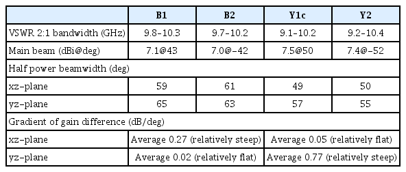
Summary of the performance of the proposed antenna integration
V. Conclusion
In this paper, we have proposed a compact, lightweight Rx antenna integration suitable for 3D direction-finding radar. The proposed antenna integration exhibits a return loss value under 9.6 dB in the frequency band range from 9.7 to 10.2 GHz. The radiation patterns of the proposed antenna in both the yz and xz planes are generally suitable for a direction-finding system. In addition, the proposed antenna integration is both compact and light. Therefore, when combined with an appropriate receiver module for extracting DC voltage, it is a good antenna candidate for a direction-finding system for an avionic object.
Acknowledgments
This research was supported by the Agency for Defense Development, Korea.
References
Biography
Hojoo Lee received his B.S. and M.S. degrees in Electronics and Computer Engineering from Hanyang University in Seoul, Korea, in 2010 and 2015. He is currently working toward a Ph.D. degree in the Department of Electronics and Computer Engineering at Hanyang University in Seoul, Korea. His current research interest focuses on various RF devices, waveguide components and antenna designs, mainly in the field of 5G mm wave and automotive application.

Jaehoon Choi received the B.S. degree from Hanyang University, Korea in 1980 and the M.S. and Ph.D. degrees from Ohio State University, Ohio, USA in 1986, and 1989, respectively. From 1989 to 1991, he was a research analyst with the Telecommunication Research Center at Arizona State University, Tempe, Arizona. He had worked for Korea Telecom as a team leader of the Satellite Communication Division from 1991 to 1995. Since 1995, he has been a professor in the Department of Electronics and Computer Engineering at Hanyang University, Korea. He has published more than 290 refereed journal articles and numerous conference proceedings. He also holds over 90 patents. His research interests include antenna, microwave circuit design, and EMC. Currently, his research is mainly focused on the design of a compact multiband antenna for mobile wireless communication and antennas for biomedical applications.

Jaesik Kim received B.S. and Ph.D. degrees in radio wave engineering from Kwangwoon University and electrical and electronic engineering from Yonsei University, Seoul, Korea in 2011 and 2017, respectively. He joined Agency for Defense Development, Daejeon, Korea in 2017, where he is currently a Senior Researcher. His current research interests include direction-finding antennas and phases array antennas.
