Wide and Dual-Band MIMO Antenna with Omnidirectional and Directional Radiation Patterns for Indoor Access Points
Article information
Abstract
A wide-band multiple-input multiple-output (MIMO) antenna with dual-band (2.4 and 5 GHz) operation is proposed for premium indoor access points (IAPs). Typically, an omni-directional pattern is used for dipole antennas and a directional radiation pattern is used for patch antennas. In this paper, both antenna types were used to compare their performance with that of the proposed 2 × 2 MIMO antenna. We simulated and measured the performance of the MIMO antenna, including the isolation, envelope correlation coefficient (ECC), mean effective gain (MEG) for the IAPs, and the throughput, in order to determine its communication quality. The performance of the antennas was analyzed according to the ECC and MEG. The proposed antenna has sufficient performance and excellent characteristics, making it suitable for IAPs. We analyzed the communication performance of wireless networks using the throughput data of a typical office environment. The network throughput of an 802.11n device was used for the comparison and was conducted according to the antenna type. The results showed that the values of the ECC, MEG, and the throughput have unique characteristics in terms of their directivity, antenna gains, isolation, etc. This paper also discusses the communication performance of various aspects of MIMO in multipath situations.
I. Introduction
The rapidly increasing demand for broadband traffic is driving the need for cellular networks with higher capacity. In these communication systems, high data transmission rates and low bit error probability are common requirements [1–3]. Multiple-input multiple-output (MIMO) systems have been broadly investigated because they can increase the channel capacity without sacrificing additional spectra [4]. Multiple antennas, which are used in wireless local area networks (WLANs), can increase the channel capacity [5]. Several antennas have been designed with various patterns for indoor access points (IAPs). Omnidirectional antennas (such as dipole antennas) and directional antennas (such as patch antennas) are generally useful for a variety of access points (APs), because the radiation patterns of these antennas allow for good transmission and reception from mobile units. Omni-directional antennas feature a radiation pattern that is nearly symmetric [6–8]. The directional pattern in patch antennas affects the radio frequency (RF) coverage by focusing the bulk of the RF energy in a specific direction [9, 10]. Dual bands with a broad bandwidth are advantageous for wireless networks in order to allow a greater number of devices to share the available space. However, dipole and patch antennas typically have a narrow bandwidth, and it is particularly difficult to implement a dual-band (2.4 and 5 GHz) patch antenna with a wide band. Several researchers have studied the communication performance of WLANs using the 802.11 MAC protocol. The throughput performance of the 802.11 WLAN has been simulated using many interesting methods. Modelling the throughput performance in a WLAN involves studying parameters such as the packet length and the transmission rate [11, 12]. However, researchers have validated only a predictive model and simulated data transmission with different packet lengths and hotspots [13]. Other researchers have evaluated performance according to different clients with representative 802.11 chipsets [14]. In addition, throughput data has been simulated in terms of beam patterns in a scattering environment [15]. However, no studies have measured throughput data in real multipath conditions or analyzed MIMO performance.
In this paper, two typical antennas that represent omnidirectional and directional radiation patterns were designed to compare the performance of these antennas with that of MIMO in an IAP. The antennas were composed of dual bands (2.4 and 5 GHz) and designed according to their radiation pattern. The frequency covers the entire WLAN band (IEEE 802.11b/g and 802.11a/j) and the antennas have sufficient gain and beam coverage to be applied to a premium access point, which requires the antenna to operate in the full frequency band for WLAN service. First, the dipole antenna with omni-directional pattern was designed. Then, the dipole antenna was designed using back-to-back radiators. The dipole antenna was arrayed to enhance the gain and was optimized with a transformer. The proposed omni-directional antenna operates over a broadband and covers nearly 360 degrees. Further, a dual-band, slot-coupled, patch antenna with a directional pattern was designed. Radiation was used to focus the radio signal in order to direct the energy in specific directions. Patch antennas are generally recommended to be placed down hospital hallways or office corridors. To improve the directivity of the proposed antenna, we used parasitic elements and a reflector. The proposed antenna enhanced the bandwidth by more than 18% at the 5 GHz band [16]. High isolation and a low envelope correlation coefficient (ECC) are required in MIMO systems [17–20]. We analyzed the isolation and the ECC. The mean effective gain (MEG) of the antenna elements has been widely used to describe the diversity performance of multiple-antenna systems in random multipath, which exist in reflection, diffraction, and scattering. The proposed MIMO antenna has high isolation, a low ECC, and a high enough MEG. Next, we evaluated the throughput performance of WLANs according to the gain, directivity, and isolation in a real office environment.
II. Proposed Antenna Structure
1. Dipole Antenna with an Omni-directional Radiation Pattern
Fig. 1 shows a perspective drawing of the dipole antenna. Each dipole is optimized for 2.4 GHz and 5 GHz and includes the upper and lower portions of the antenna, such that the antenna is operable as a standard half-wavelength dipole antenna. In order to maximize the gain of the proposed antenna, the radiating dipole elements were separated by a distance of 0.6λg, as shown in Fig. 1(a). The proposed structure is symmetrical on the right and left. Fig. 1(b) also illustrates the geometry and configuration of the proposed dual-band dipole antenna, which is printed on a 0.8-mm thick RF30 (Taconic Inc.). The top plane consists of high-band (5 GHz) and low-band (2.4 GHz) radiating elements; the line of the high-band element is 11 mm, and the line of the low-band element is 23 mm. The distance between the high-band elements is 8 mm and the distance between the low-band elements is 11 mm. A quarter-wave transformer was implemented to match the 70.7 Ω and 100 Ω lines with the 50 Ω microstrip line. The width of the quarter-wave transformer was optimized for each characteristic impedance. The 100-Ω line is 20.7 mm, the 70.7-Ω line is 4 mm, and the 50-Ω line is 12.3 mm. The impedance of the 100-Ω line was divided into the 50-Ω line. The ground width of the bottom plane is 2 mm. To improve the impedance of the proposed antenna, we used the stub elements, S1 and S2, at the bottom plane. Both S1 and S2 are configured with λg/4 open stub. S1 is 3 mm × 1.8 mm, and it was placed 13.9 mm away from the feed. S2 is 6 mm × 2 mm, and was placed 31 mm from the feed. The detailed feeding structure is shown in Fig. 1(c); the feed of the bottom plane is connected to that of the top plane. The antenna array is composed of two dipole antenna elements. The two microstrip lines used for the array configuration were printed on the top layer. As shown in Fig. 1(c), if the input port impedance of P0 is Z0 (50 Ω), and the two output ports have the same impedance of Z1 = 2 × Z0 (100 Ω), then the input power can be equally divided into the output ports. The MIMO antenna is composed of four dipole antennas with a 2 × 2 structure. The overall size of the MIMO antenna is 160 mm × 160 mm, as shown in Fig 1(d).

Dipole antenna: (a) dipole antenna, (b) top and bottom, (c) side, and (d) MIMO antenna.
The distance between the two radiators is 0.67λg (80 mm) at the 2.4 GHz band and 1.3λg (80 mm) at the 5.4 GHz band. The fabricated dipole antenna is shown in Fig. 2. The electric energy density of the antenna is shown in Fig. 3. The electric energy shows that each high and low-band radiating element plays a role in determining the operating frequency.
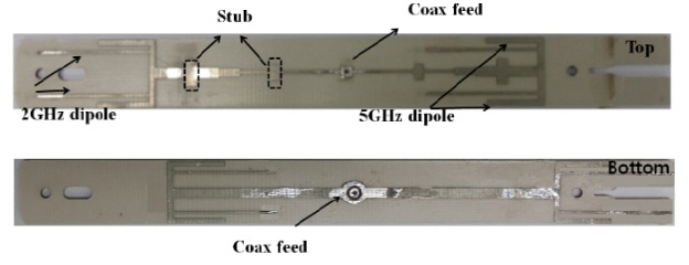
Dipole antenna fabricated for an indoor access point.
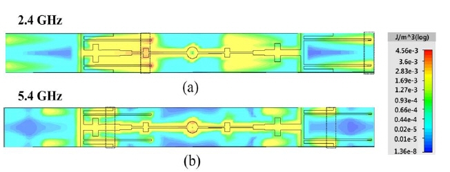
Electric energy density (J/m3) of the dipole antenna at the 2.4 GHz (a) and 5.4 GHz (b) bands.
2. Patch Antenna with a Directional Radiation Pattern
The configuration of the proposed patch antenna is shown in Fig. 4 and that of the slot antenna is shown in Fig. 4(a) [21]. The size of the reflector is 80 mm × 80 mm. The substrate that the first radiator was printed on was an RF 30 by Taconic Inc. with a 0.8 mm thickness and relative permittivity (ɛr) of 2.9. The size of the substrate is 56 mm × 56 mm. It is configured as a bow-tie shape to enhance the bandwidth at the 2 GHz band. The dimension of the slot with the bow-tie shape is 39.4 mm × 6 mm so it can operate at 2.4 GHz. The length of the feed line on the slot antenna is 29.5 mm and the width of the feed line is 2 mm, for a characteristic impedance of 50 Ω. The radiator size of the patch antenna of the second radiator operating at the 5 GHz band is 60 mm × 60 mm, and the rectangular patch (P1) on the center of the second radiator is 14 mm × 14 mm. This antenna was printed on a 1 mm thick substrate (FR-4: ɛr = 4.4, tan δ = 0.02) [22]. All metal was etched with copper, and the depth of etching copper is 17.5 μm (0.5 oz). The patch is usually 0.3333λ < Length < 0.5λ, where λ is the free-space wavelength. The patch is designed to be very thin such that t < < λ (where t is the patch thickness). The height h of the dielectric is usually 0.003λ ≤ h ≤ 0.05λ [23]. The optimized dimensions of the four parasitic patches (P2) are 15.5 mm × 15.5 mm and they are separated from the rectangular patch (P1) by 0.5λg at the 5 GHz band (7.5 mm). The chocks (28 mm × 1 mm) were etched on the patch antenna with a gap of 1 mm from the parasitic patch (P2). The azimuth beam width is wider than the elevation beam width. The chock of the second radiator decreases the beam width of the azimuth. Controlling the beam width can improve isolation among the radiators in MIMO structures. A side view of the proposed antenna is shown in Fig. 4(b). The distance between the slot antenna and the reflector is 6 mm, and the distance between the first and second radiator is 5 mm (1/8λg at the 5 GHz band). The MIMO antenna is composed of four patch elements, as shown in Fig 4(c). The MIMO antenna overall is 160 mm × 160 mm. The distance among the patch radiators is 0.67λg (80 mm) at the 2.4 GHz band and 1.3λg (80 mm) at the 5.4 GHz band. The fabricated patch antenna is shown in Fig. 5, and the electric energy density is shown in Fig. 6. As pictured, the electric energy density of the rectangular patch (P1) is transferred to the parasitic patch (P2) by coupling. The simulation showed that parasitic patches play a role in determining the bandwidth at the 5 GHz band.
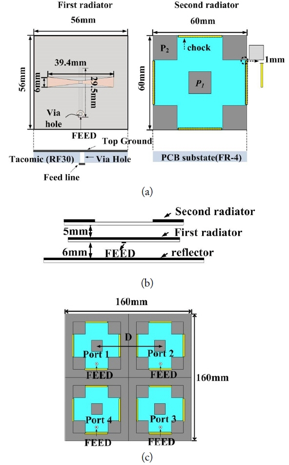
Patch antenna: (a) top, (b) side, and (c) MIMO antenna.

Patch antenna fabricated for an indoor access point.
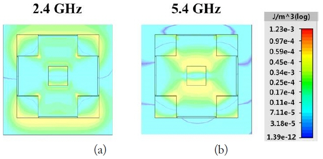
Electric energy density (J/m3) of the patch antenna at the 2.4 GHz (a) and 5.4 GHz (b) bands.
III. MIMO Performance of the Proposed Antenna
The MEG was defined in [24] as the ratio between the mean received power of the antenna and the total mean incident power. It can be calculated by (1):
The expression for the MEG can be rearranged as the following equation:
where Gθ (θ, φ) and Gφ (θ, φ) are the θ and φ components of the antenna power gain pattern, respectively, and Pθ (θ, φ) and Pφ (θ, φ) are the θ and φ components of the angular density functions of the incoming plane waves, respectively.
We analyzed MEG according to the propagation models. The wireless channel is modelled to specify the incident field in the form of an angular density function. In this paper, we used the typical model of an incident field using both the uniform spread in the azimuth angle and Gaussian spread in elevation angle according to the general method of MIMO measurement. The statistical distribution of Gaussian in the elevation angle (θ) is determined by the following equation:
Also, the statistical distribution of uniform in azimuth angle (Φ) is determined by the following equation:
where mv and mh are, respectively, the mean elevation angle of each vertically polarized and horizontally polarized wave distribution observed from the horizontal direction. In addition, σ refers to the standard deviation of the vertical (σv) and horizontal (σh) wave distributions, respectively. The angles of the scenario parameters of the indoor environment are mv = 20°, mh = 20° and σv = 30°, σh = 30°, respectively. The antenna branch power ratio is MEG1/MEG2. In a good diversity system, the power levels of the signals received by the two antennas are similar. The ECC (ρe) between the two antennas can be calculated from the following complex correlation coefficient.
where Eθ and Eφ denote the θ and φ polarized electric fields of the antennas. The correlation coefficient of the signals is related to the propagation environment and the radiated far-field characteristics. The relationship between the complex cross-correlation coefficient ρ and the ECC (ρe) is obtained with |ρ|2 ≅ρe.
1. Measured Result of the MIMO Antenna with the Dipole Antenna with an Omni-directional Pattern
Fig. 7 shows the measured isolation (S12, S13, and S14) and the reflection coefficient (S11, S22, S33, and S44) of the MIMO antenna. The return losses are less than -10 dB over the operating frequency band (2.4–2.48 GHz and 4.905–5.845 GHz). The proposed dipole antenna has a sufficiently broad bandwidth to satisfy the full band set by IEEE 802.11 standards. The feed point distance from the primary antenna is 0.67λg (80 mm) at the 2.4 GHz band for best isolation. The isolation is below -15 dB over the operating frequency band. However, in the case of S13 (isolation), it has good isolation compared to other ports, as the distance between port 1 and port 3 is longer than that between ports 1 and 2 or ports 1 and 4. Fig. 8 shows the measured radiation patterns of the proposed antenna according to the ports. In addition, Fig. 8 shows the radiation patterns in the Y–X plane (0° ≤ Φ ≤ 360°) and X–Z (0° ≤ θ ≤ 360°) plane at 2.44 GHz and 5.4 GHz. The radiation pattern of the proposed dipole antenna shows omni-directional characteristics and the measured peak gains of the ports are similar. Fig. 9 shows the measured peak gains and radiation efficiencies of the dipole antennas in the operating frequency bands. The peak gain of each port is 4.6–5.07 dBi at the center frequency (2.44 GHz) of the 2.4 GHz band and 6.24–6.5 dBi at the center frequency (5.4 GHz) of the 5 GHz band. The radiation efficiencies of each port are higher than 69% at 2.44 GHz and 66% at 5.4 GHz. The results show that the dual-band omni-directional antenna achieves a high antenna gain and provides a wide bandwidth while maintaining a compact size. Table 1 shows ECC characteristics of the dipole antennas according to the frequency. The ECC can be calculated from the S-parameter with (5). The isolation (S12) improves as the distance between the proposed antennas increases. The ECC value for the high band (i.e., the 5.4 GHz band) is lower than that for the low band (i.e., the 2.42 GHz band), as the spatial separation of the two antennas is large at high frequencies (>1λ). The measurement results of diversity parameters for the dipole antenna using a Gaussian spread are shown in Table 2. The MEG ratio is close to 1 dB. The MEG values of each antenna are less than 0.1 dB [18]. As expected, the value of the MEG ratio between port 1 and port 3 performs better compared to the MEG ratio with other ports. The other two MEG ratios for ports 1 and 2 and ports 1 and 4 show almost equally good characteristics. Each port has similar MEG values favorable for an independent channel in a multipath environment [25].
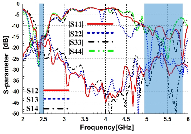
S-parameter of the dipole antenna.
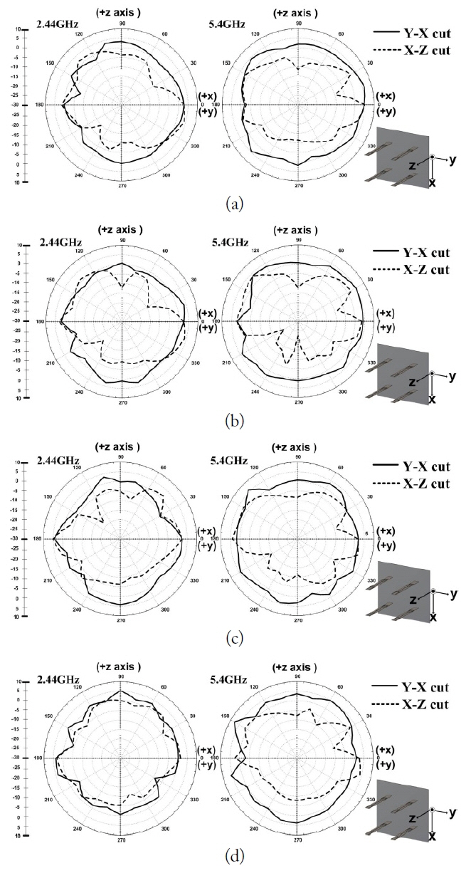
Radiation pattern of the dipole antenna: (a) port 1, (b) port 2, (c) port 3, and (d) port 4.

Measured gain and radiation efficiency characteristics of the dipole antennas.

Measured ECC characteristics of the dipole antenna according to the frequency

Measured results of diversity parameters for the dipole antenna using Gaussian spread

Measured ECC characteristics of the patch antenna according to the frequency
2. Measured Result of the MIMO Antenna with a Patch Antenna of in Directional Pattern
The measured reflection coefficient (S11) of the proposed MIMO antenna is shown in Fig. 10. The distances between the antennas are 0.67λg (80 mm) at 2.4 GHz and 1.3λg (80 mm) at 5 GHz. The measured return-loss result is almost equal to that of the reference antenna. The S11 of the antennas is less than −10 dB (VSWR 2:1) at 2.4 GHz and 5 GHz. Patch antennas typically have a narrow bandwidth. However, the proposed antenna improved the bandwidth with the use of a coupled feed and a parasitic element structure at the operating frequency. The isolation between each feed is also less than −15 dB over the operating band. The isolation (S13) is better than the isolation between other ports like a dipole. In addition, the isolation performance (S12) in the parallel condition is better than that in the series (S14) condition due to the distribution of the E/H-field. When the proposed antennas are located in a series, the E-field is created by a positive charge and a negative charge like a dipole at the center. As a result, the main beams are directed toward each other face-to-face due to the electric field. When the proposed antennas are parallel to one another, the main beam is relatively directed in the opposite direction plane because the H-field is canceled at the center [26].
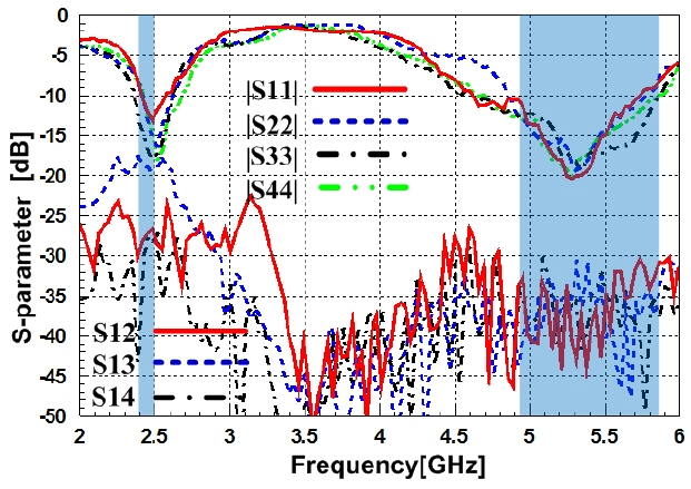
S-parameter of the patch antenna.
Fig. 11 shows the radiation patterns in the azimuth (Y-Z plane) and the elevation (X-Z plane) planes at 2.44 GHz and 5.4 GHz. In the elevation plane pattern, the angle starts from the +x direction. The major lobe directed the signal at the +z direction (90°) and in the azimuth plane, the angle starts from the +y direction.
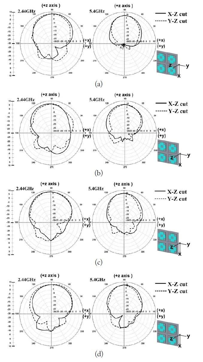
Radiation pattern of the patch antenna: (a) port 1, (b) port 2, (c) port 3, and (d) port 4.
Fig. 12 shows the measured peak gains and radiation efficiencies of the patch antennas in the operating frequency bands. The peak gain of each port is 6.7–7.24 dBi at 2.44 GHz and 10.26–10.9 dBi at 5.4 GHz. The radiation efficiencies of each port are higher than 80% at both 2.44 GHz and 5.4 GHz frequency. The correlation characteristics show a low ECC (<0.5) at 2.42 GHz and 5.4 GHz, respectively. The measurement results of diversity parameters for the patch antenna using a Gaussian spread are shown in Tables 4. It shows an equally good MEG value with a low ECC as the result of the dipole antenna. As a result, the best correlation and MEG are obtained for the MIMO system.
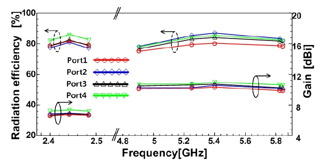
Measured gain and radiation efficiency characteristics of the patch antennas.
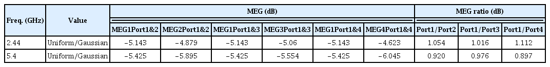
Measured results of diversity parameters for the patch antenna using Gaussian spread
3. Measured Result of the Throughput Performance of the Wireless Networks
In data communication systems, throughput is traditionally defined as the ratio of the amount of data over the time needed to transfer it. Thus, we use the general formula:
We define “received data” as the amount of 802.11 payload data successfully received by the destination node expressed in number of bits. The test was set up in a small room in a general office. The office’s dimensions are 6.3 m × 9 m, as shown in Fig. 13(a). The RX is composed of a MIMO antenna with 802.11n support. The dipole and patch antennas of the TX are configured based on a ceiling mount as a general structure. The throughput depends heavily on its environment, including the distance between the client and the IAP, the presence of radio channel interference, obstacles such as furniture, walls etc., and signal reflections like scattering. Therefore, it was necessary to limit the impact of external factors that interfere with the IAP. Any radio devices that might interfere with the throughput were removed, and the internal and external conditions, including all physical obstacles, the RF environment, and temperature conditions, were fixed.
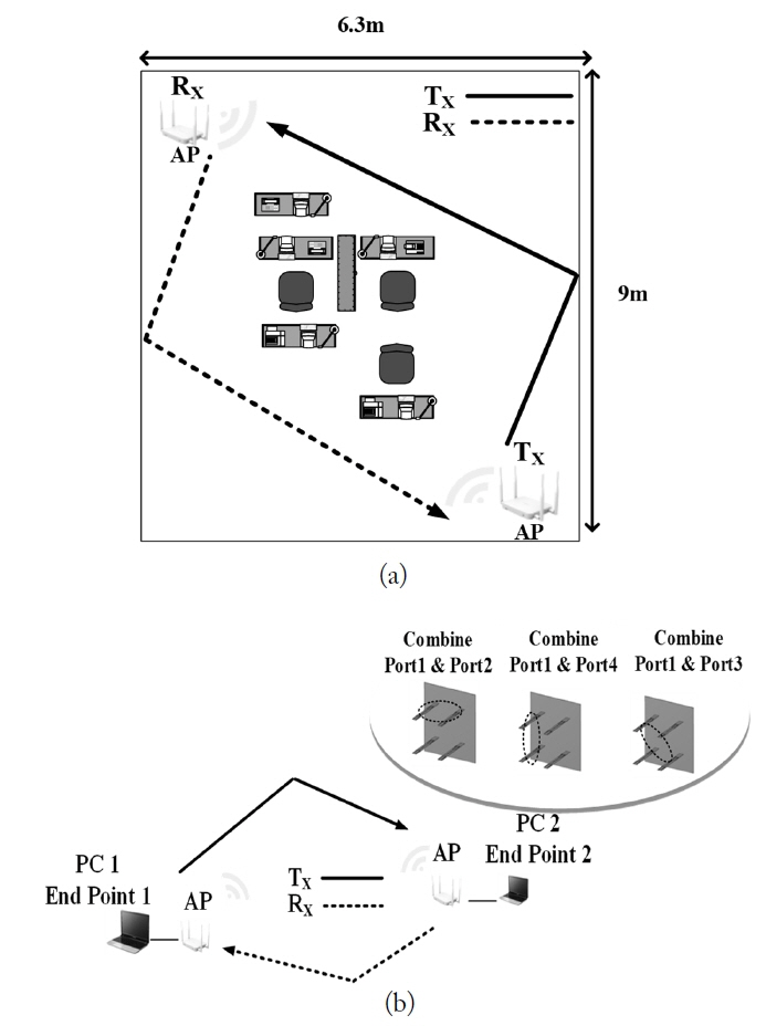
The throughput measurement of wireless networks: (a) experimental and (b) block diagram.
We focused on comparing the performance of the throughput according to three main factors: the beam pattern, the antenna gain, and the isolation between the ports. A block diagram of the throughput measurements is shown in Fig. 13(b). All tests were measured using the Chariot program of Ixia Inc. The PC 1 at TX is composed of Endpoint 1 and the IAP with 2 × 2 MIMO, and the PC 2 at RX is composed of Endpoint 2 and the IAP with the proposed antenna. In addition, the IP addresses differed for the test runs. For example, when 192.168.0.1 was assigned to Endpoint 1 in the test run, Endpoint 2 was assigned to 168.168.0.2. The IAP of PC 1 sends a test signal to Endpoint 1. When all the endpoint pairs were ready, the two endpoint computers executed the test. The Endpoint 1 computer collects the test results and timing records and sends them to IxChariot [27, 28]. The IAP chipset at the TX was the RTL8197D (Realtek Inc.) and the chipset of the wireless LAN card at the RX was RTL8812AU (Realtek Inc.).
In order to equalize the conditions, we used the same PC and IAPs with wireless cards for all the tests, and the same packets with loads of 9.53 Mbytes. Fig. 14(a) shows the graph of a typical Transmission Control Protocol (TCP) throughput test with the dipole antenna, which is an omni-directional radiation pattern. It is necessary to compare data throughput according to the directional and omni-directional patterns, which are typical radiation patterns for the general APs. The test was conducted consistently according to the different types of radiation patterns showing good isolations in the indoor condition. The experiments were run three per port, and the average value was recorded. The data packet cycle was run 180 times. Using a large time unit, we measured the average capacity of the IAP [29]. When the antennas at port 1 and port 2 were combined, the average throughput was found to be 139.13 Mbps. The measured throughput data of ports 1 and 3 combined was 149.8 Mbps, and the throughput data measured by combining ports 1 and 4 was 141.6 Mbps. The results of the TCP performance was similar to that of the port when isolation was high (less than −15 dB) over the operating frequency band; however, ports 1 and 3 had slightly better TCP performance compared to the other ports, as the isolation between ports 1 and 3 was better than that for the other ports.
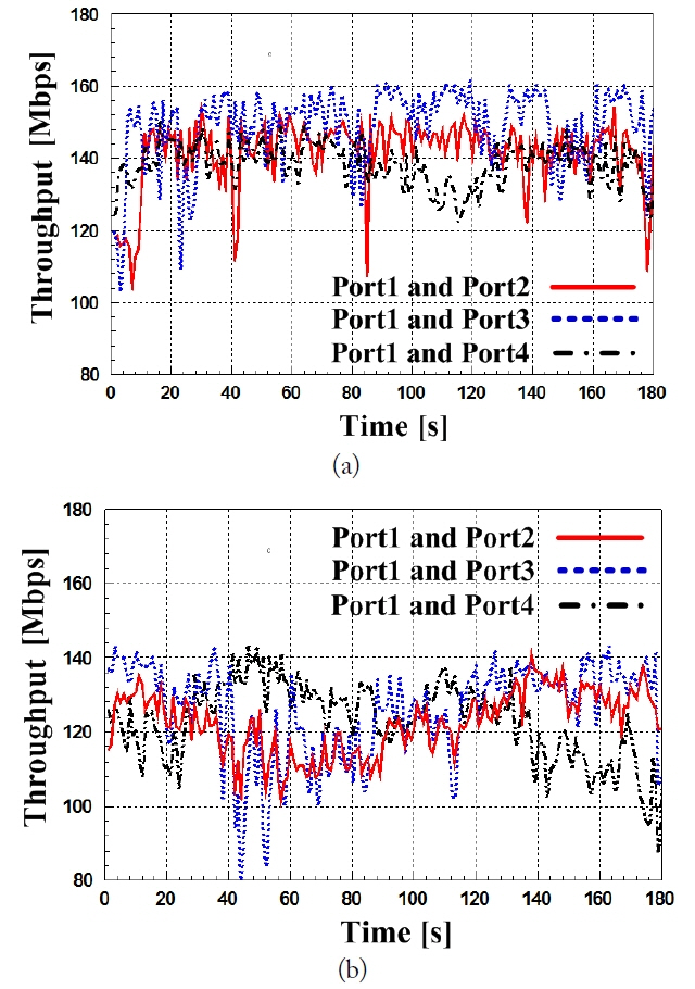
Typical TCP performance of the IAP: (a) dipole antenna and (b) patch antenna.
Fig. 14(b) shows the typical TCP performance of the IAP with a patch antenna, which has a typical directional pattern. When the antennas at ports 1 and 2 were combined, the average throughput was 122.4 Mbps. The measured throughput data of ports 1 and 3 combined was 126.5 Mbps, and the throughput data measured by combining ports 1 and 4 was 123.5 Mbps. In wireless telecommunications, multipath is the result of radio signals reaching the receiving antenna by two or more paths. In multipath environments, the diversity of the antennas involved affects the throughput data. The patch antenna with a relatively high gain has poor throughput data compared to the dipole antenna in an office environment. As the total power received by the antenna is the sum over the arriving planes waves from the distribution of the angles, it is shown that the directive antenna as a patch enhances a relatively small number of incident waves. Therefore, the overall power is dependent on the angle of arrival and that received by the directive antenna is lower [15]. In an office environment, the dipole antenna with omnidirectional characteristics covers a wide area and has a higher maximum throughput compared to patch antennas.
IV. Conclusion
In this paper, we designed a wide and dual-band MIMO antenna with an omnidirectional and directional radiation pattern for premium IAPs. We analyzed the MIMO performance using two types of antennas in the 2 × 2 MIMO system. The optimized frequencies were 2.4–2.4835 GHz and 4.905–5.845 GHz. In order to analyze the proposed MIMO antenna for the IAPs, we simulated and measured the isolation. The isolation was below −15 dB. The proposed MIMO antenna has a low ECC (<0.5) with low correlations in a comparative analysis. The values of the MEG between the two antenna elements are less than 0.5 dB. The proposed MIMO antenna supports 802.11n and is capable of providing a high-quality IAP. Finally, we analyzed the throughput performance according to the radiation pattern, the antenna gain, and the isolation using the proposed antenna in an office area. We have shown that the MIMO antenna with an omni-directional pattern can improve throughput data in office environments with multipath. The results of this study should apply to 4 × 4 MIMO systems and provide guidance on the selection of suitable types of antennas for certain environments and particular purposes.
Acknowledgements
This work was supported by a grant from the National Research Foundation of Korea, which is funded by the Korean government (No. 2016R1D1A1B02012957).
References
Biography
Insu Yeom received his B.S. and M.S. degrees in electrical engineering from Seoul National University of Science and Technology (SeoulTech), Seoul, Korea, in 2002 and 2011. He also obtained a Ph.D. in electrical engineering from SeoulTech, Korea, in 2017. His current research interest focuses on MIMO antennas, reconfigurable antennas, and RF energy for heating systems.

Young-Bae Jung received a B.S. in radio science and engineering from Kwangwoon University, Seoul, Korea, in 1998, and M.S. and Ph.D. degrees in information and communications engineering from Korea Advanced Institute of Science and Technology (KAIST), Daejeon, Korea, in 2001 and 2009, respectively. From 2001 to 2011, he was with the Electronics and Telecommunications Research Institute (ETRI), Daejeon, Korea, as a senior researcher. From March 2011, he has been an associate professor in the Department of Electronics and Control Engineering, Hanbat National University, Daejeon, Korea. His work is focused on active phased array antenna systems and next generation mobile base-station antennas. His research interests include active phased array antenna systems and active/passive components in the field of RF and microwave.

Chang Won Jung received his B.S. degree in radio science and engineering from Kwangwoon University, Korea, in 1997 and his M.S. degree in Electrical Engineering from the University of Southern California, Los Angeles, USA, in 2001. He also obtained a Ph.D. in electrical engineering and computer science from the University of California, Irvine, USA, in 2005. Since 2008, he has been a professor with the Graduate School of Nano·IT·Design Fusion, Seoul National University of Science and Technology. From 1997 to 1999, he was a research engineer in the wireless communication department of LG Information and Telecommunication in Korea. From 2005 to 2008, he was a senior research engineer in the communication laboratory of Samsung Advanced Institute of Technology, Korea. His research interests include antennas for MMMB communication systems, multifunctional reconfigurable antennas, EMI/EMC, millimeter-wave applications, wireless power transfer for energy harvesting, transparent RF passive components etc.