SDR-Based Frequency Interference Emulator in the Space-Time Domain and Its Application
Article information
Abstract
In this study, we propose a software-defined radio-based frequency interference emulator in the space-time domain. This emulator can easily model actual interference environments because of the versatile programming capability of the universal software radio peripheral and LabVIEW. As an example of an interfering network using the contention-based multiple access scheme in the time domain, we emulate a coordinated Wi-Fi network that consists of one access point and two Wi-Fi nodes. Results show that our emulator can successfully model multiple interfering signals in the Wi-Fi network and easily adjust various space–time domain parameters.
I. Introduction
A world without wireless communication is difficult to imagine. For various wireless services, wireless devices such as smart phones, laptops, and sensors are rapidly increasing, thus causing the use of the frequency spectrum to increase sharply. However, only a limited amount of frequency spectrum is available, and this limitation may cause wireless devices to experience adverse interference from nearby wireless devices that simultaneously transmit in the same or adjacent frequency band. Therefore, a quantitative understanding and analysis of this interference are important for future wireless services [1].
Various experimental methods to analyze interference problems are reported in [2–5]. Some studies use real wireless hardware to emulate interference environments [2–4]. However, when real hardware is used, changing or obtaining physical (PHY) and/or media access control (MAC) layer parameters is difficult because they are commonly embedded in the modem chip. A typical parameter in interference analysis, namely, bit error rate, can hardly be measured at the PHY layer of real hardware without modifying its software. One study generally used signal generators to emulate interfering signals [5].
Although a signal generator is highly controllable, the number of interferers that it can emulate remains unclear. Therefore, a necessary task is to implement an interference emulator that can reflect a realistic interference environment and easily adjust various parameters of multiple interferers in the space, frequency, and/or time domain.
This study aims to develop a versatile emulator for imitating various frequency interference environments consisting of multiple interferers. We propose a software-defined radio (SDR)-based frequency interference emulator in the space–time domain. In our emulator, space and frequency domain parameters in the PHY layer are adjusted by a Universal Software Radio Peripheral (USRP) and the LabVIEW program. Time domain parameters used in the MAC layer are controlled by a discrete Markov model implemented in the LabVIEW program. Given the versatile programming capability of USRP and LabVIEW, we can adjust various space and frequency domain parameters (separation distance, path loss according to the separation distance, center frequency, bandwidth, spectrum mask, transmit power, etc.) and time domain parameters (packet size, duty cycle, back-off time, etc.), respectively. Accordingly, we analyze the effects of the victim’s performance degradation due to realistic multiple interferers in a given interference scenario.
II. Interferer Model
To show an explanatory emulation of a multi-interferer environment in detail, we assume an interference scenario with Zigbee as the victim and the Wi-Fi network as the multiple interferers. We take these assumptions because the 2.4 GHz unlicensed frequency band is used worldwide, and previous studies showed that the Wi-Fi network is the most significant interference source of Zigbee [2]. Fig. 1 depicts a typical interference scenario with Wi-Fi and Zigbee devices in the space and time domain, respectively. In the space domain, the probability of interference increases as the separation distance between the victim’s wireless device (Zigbee) and the interferer (Wi-Fi) decreases. Moreover, the interference may occur as the operating frequency band between wireless devices overlaps. As shown in Fig. 1(a), the Zigbee channel may overlap with the Wi-Fi channel. For example, if the Wi-Fi network operates on channel 6 (CH6) and Zigbee operates on channel 17 (CH17), then the Zigbee channel will be completely overlapped by the Wi-Fi channel. This interference is probably the most severe because the spectrum overlapping factor is almost 1. To extend this finding to a case with K Wi-Fi interferers, the received interference signal power at the victim’s antenna input port can be defined as
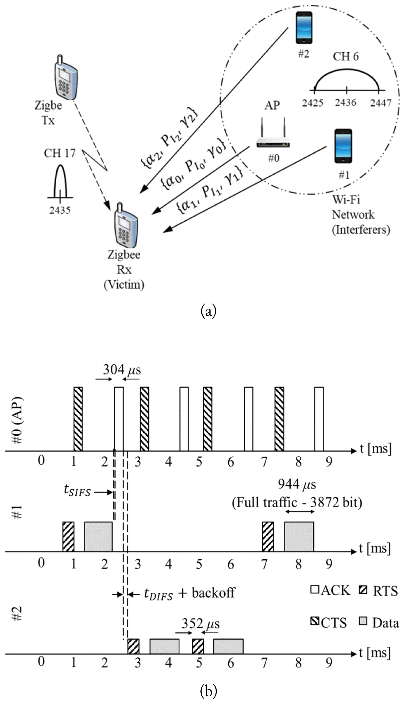
Interference scenario that consists of a Zigbee pair as the victim and three Wi-Fi interfering nodes. (a) Space domain and (b) time domain.
where Pwifi is the transmit power of the WiFi node, and αk(d) is the path loss at the distance, d, from the kth node to the victim receiver, γk and is the spectrum overlapping factor of the kth Wi-Fi interferer; the typical values of γk and αk are specified in [6]. An important detail is that even though K Wi-Fi interferers exist, only one node including the access point (AP) transmits data at any instant, as shown in Fig. 1(b).
We then consider the time domain shown in Fig. 1(b). Both standards for Zigbee (IEEE 802.15.4) and Wi-Fi (IEEE 802.11b) specify three clear channel assessment (CCA) methods to determine the channel occupancy. The CCA default mode of Wi-Fi and Zigbee devices operate in the carrier sensing mode, in which a Wi-Fi node will consider the channel free if no other Wi-Fi device is detected. If we assume that both Wi-Fi and Zigbee devices operate in the carrier sensing mode, then they will essentially be blind to each other’s transmissions[7-8]. This assumption provides the worst-case performance of an environment in which Wi-Fi and Zigbee coexist [9]. Therefore, the interfering Wi-Fi network can be emulated independently regardless of the Zigbee victim nodes. Moreover, only one Wi-Fi node may transmit at any instant, and it interferes with the Zigbee nodes regardless of the number of coordinated Wi-Fi nodes. Fig. 1(b) shows an example in which the Wi-Fi network has full traffic, where tDIFS and tSIFS are the periods of time for the distributed interframe space (DIFS) and the short interframe space (SIFS), respectively. If the channel is idle for a period of time that is equal to tDIFS, node #1 will transmit the Request-to-Send (RTS) message. If node #1 receives the Clear-to-Send (CTS) message from AP, then node #1 will transmit its data packet. In case of full traffic, the packet size is 3872 bit (about 944 μs). It the AP successfully receives the packet from node #1, the AP transmits the acknowledgement (ACK) message to node #1 after the tSIFS second. This process is repeated until there is no data packet to be transmitted.
III. Implementation of Interference Emulator
We designed an SDR-based frequency interference emulator that consists of one Wi-Fi AP and two Wi-Fi nodes, as shown in Fig. 2(a). We connected the host PC to the USRP with gigabit Ethernet cables for a fast interface, and we used an RF switch that can selectively connect three antennas with one USRP. The Wi-Fi transmitter output power is set to 30 mW in accordance with the standard. Our emulator can change the individual path loss αk according to the distribution of the nodes. Moreover, the proposed emulator can calculate path loss in the software by using a specific path loss model without the actual spatial distribution of the interferers. That is, as shown in Fig. 1(a), if we determine the spatial distribution of interferers and calculate path loss in the software, then we can easily implement our emulator using only one USRP. For this reason, the suggested emulator is advantageous for emulating multi-interferer environments.
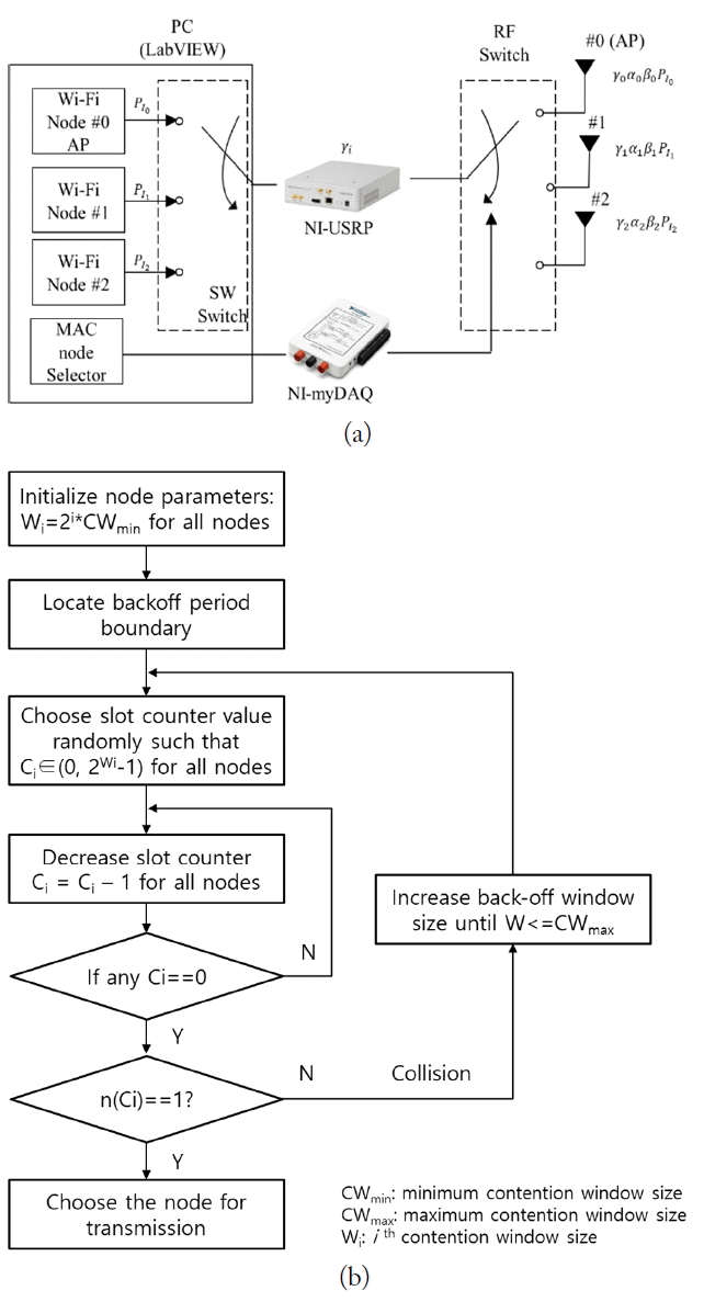
Block diagram of the interference emulator. (a) Block diagram and (b) transmitting node selection algorithm.
In the time domain, a transmitting node selection algorithm is implemented using LabVIEW. According to the channel access scheme of the Wi-Fi network, if more than two nodes transmit data at a given instant, then a collision will occur, and the collided nodes will have to wait during the slot counter value, Ci, where the subscript i denotes the backoff stage, i ∈ {0,1, ⋯, m}, and m is the maximum backoff stage. When only one Wi-Fi node transmits data at a given time, the Wi-Fi node transmits immediately without collision. Otherwise, each unsuccessful transmission doubles the contention window size, Wi, up to a maximum value, CWmax. This process is depicted in Fig. 2(b) and is based on [10].
To support the validation of our emulator, we generate interfering data packets with the LabVIEW program using the transmitting node selection algorithm depicted in Fig. 2(b). Then, we configure the emulator as shown in Fig. 3(a). In the configuration illustrated in Fig. 3(a), we expect the AP signal to have the highest amplitude at the victim receiver and the #2 node signal to have the smallest amplitude at the victim receiver. Verification of the measured waveform at the victim receiver using an oscilloscope in Fig. 3(b) confirms that our emulator can successfully generate time domain packets of multiple Wi-Fi interferers. All parameters, except for center frequency, are consistent with the Wi-Fi standard, but center frequency is set to 400 MHz because of the limitation of the oscilloscope. Fig. 3(b) shows the interference waveform of the Wi-Fi interferers when the Wi-Fi network has a full traffic case. The time domain waveform in Fig. 3(b) is almost identical to that in Fig. 1(b). To test its usability, we emulate an interference waveform when the Wi-Fi network has no traffic and the Wi-Fi AP transmits only a beacon every 100 ms, as shown in Fig. 3(c). These results show that our emulator can successfully emulate interfering signals in the Wi-Fi network and easily adjust various space-time domain parameters.

Interference emulation of the Wi-Fi network at the input of the victim receiver. (a) Photograph of the implementation, (b) full traffic case, and (c) no traffic case.
IV. Conclusion
We have proposed an SDR-based frequency interference emulator in the space-time domain. Actual interference environments can be modeled easily because of the versatile programming capability of the USRP and LabVIEW. Our interference emulator can easily model a large number of simultaneous interferers that are correlated. The emulator can also help with the requirements of the extensive and controlled testing of the frequency interference mitigation algorithm prior to its use within a system.
Acknowledgments
This work was supported by the ICT R&D program of MSIP/IITP, Republic of Korea (No. 2016-0-00141, Development of coexistence technology and analysis tool for the promotion of free band/unlicensed band).
References
Biography

Hyungoo Yoon received his B.S., M.S., and Ph.D. degrees in electronics engineering from Yonsei University, Seoul, Korea, in 1995, 1997, and 2002, respectively. From 2002 to 2004, he worked at Hyundai Electronics in Icheon, where he developed code division multiple access base stations. Since 2004, he has been a professor at the Department of Electronic Engineering at Myongji College, Seoul. His main research interests include radio resource management, interference mitigation techniques, multiple-input multiple-output systems, and spectrum engineering.

Jin-Soo Park received his B.S. and M.S. degrees in electrical engineering from Kookmin University, Seoul, Korea in 2014 and 2016, respectively. He is currently working at ZHT, where he has developed a frequency synthesizer for seekers. His current interests include anti-jamming and spectrum engineering, software-defined radio, and aerospace and defense system design.

Jungsun Um received his B.S. and M.S. degrees from Sungkyunkwan University, Suwon, and his Ph.D. degree from Korea Advanced Institute of Science and Technology (KAIST), Daejeon, Korea. Since 2006, he has been working at the Electronics and Telecommunications Research Institute (ETRI). His current research interests include spectrum sharing technologies, digital signal processing, and wireless communication systems.

Byung-Jun Jang received his B.S., M.S., and Ph.D. degrees in electronic engineering from Yonsei University, Seoul, Korea, in 1990, 1992, and 1997, respectively. From 1995 to 1999, he worked at LG Electronics, Seoul, where he developed code-division multiple-access and digital enhanced cordless telecommunication RF modules. From 1999 to 2005, he worked at the Electronics and Telecommunications Research Institute (ETRI), Daejeon, Korea, where he performed research on the fields of satellite RF components and monolithic microwave integrated circuits. In 2005, he joined Kookmin University, Seoul, where he is currently with the Department of Electrical Engineering. His research interests include RF circuit design, radio frequency identification system design, wireless power transfer system design, frequency interference modeling and spectrum engineering, and wireless sensor design.