Design of a Dual-Band Bandpass Filter Using an Open-Loop Resonator
Article information
Abstract
In this paper, we present a novel design for a dual-band bandpass filter (BPF) based on the conventional second-order, open-loop BPF. By adding series resonant circuits to the open ends of the resonator, we can create two resonant modes from the even and odd modes. One pair of the even and odd modes constitutes the upper passband, while the other pair constitutes the lower passband. By adding another series resonant circuit to the open-loop resonator, we can control the bandwidth of either the upper passband or the lower passband. We can replace the series resonant circuits with simple microstrip line resonators. A dual-band BPF working at both Wi-Fi bands (2.4 GHz and 5.8 GHz bands) is designed based on the proposed method and is tested. The measured and simulated results show excellent agreement.
I. Introduction
Recently, the rapid increase in wireless data traffic has resulted in the need for more bandwidth where the aggregation of the scattered allocated frequency bands is inevitable. Even though the wideband design of most radiofrequency (RF) components is essential, the bandpass filter (BPF) must have multi-bandpass performance. Therefore, many researchers have concentrated on multiband BPF designs. Most such designs are based on multiband resonators, which can be classified into lumped types, interdigital types, stub loaded types, and coupled line types [1–5]. Of these, the simplest design is based on the ring resonator, which was first introduced as early as 1972 [6]. Using simple perturbation, two resonant modes are separated and two-pole BPFs are designed. Based on the resonance characteristics, an extension to the dual-band BPF has been studied [7–11]. However, in most designs, the passband bandwidths cannot be controlled separately or an increased number of resonators is required to accommodate multiple passbands. In this paper, we propose a novel dual-band BPF based on the conventional dual-mode BPF. The perturbed open-loop resonator supports an even and an odd mode, resulting in second-order bandpass characteristics (Fig. 1). By adding two LC series resonators to the open ends of the perturbed open-loop resonator, we obtain two split even and two split odd modes, which constitute in dual-band bandpass characteristics. However, in this design, two passband bandwidths cannot be controlled separately. We add another series resonator to this configuration to control one of the passband bandwidths. Therefore, one of the passbands has three resonant modes, which results in third-order bandpass characteristics (Fig. 2).

Conventional open-loop dual-mode bandpass filter. (a) Schematic layout, (b) even-mode equivalent circuit of (a), and (c) odd-mode equivalent circuit of (b).
II. Analysis of Conventional Open Loop Dual-Mode Bandpass Filter
A conventional open-loop BPF is shown in Fig. 1. Using a short stub, we can create two resonant modes (even and odd modes) that can be derived from the equivalent circuit in Fig. 1(b) and (c). The even mode resonant frequency depends on the perturbing stub length θp, while that of the odd mode remains unchanged. The input admittances of two modes at the feed point are derived as
and
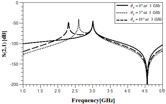
where β is the phase constant along the line and λ is the wavelength at the resonant frequency of the unperturbed open-loop resonator. The half-wavelength resonator is designed at 3 GHz, and its simulated resonant characteristics are shown in Fig. 3. As expected, only the resonant frequency of the even mode is affected by the length of the perturbing stub. As the length of the stub increases, the resonant frequency of the even mode is shifted downwards.
III. Design of Dual-Band Bandpass Filter
1. Open-Loop Resonator with Two Added Series Resonators
Two series resonators are added to the open ends of the conventional open-loop resonator, as shown in Fig. 4(a). Its even and odd mode equivalent circuits are presented in Fig. 4(a) and (b). The resonant conditions for the even and odd modes are derived from the input admittances at the feed point as

Proposed open-loop dual-band dual-mode bandpass filter. (a) Schematic layout, (b) even mode equivalent circuit of (a), and (c) odd mode equivalent circuit of (a).
and
where the resonant frequency of the LC resonant circuits (Ladded and Cadded) are set to the mid-frequency range between the passbands because the series circuit creates a transmission zero between the passbands. As the series resonant circuit is working as an inductor at the lower passband while working as a capacitor at the higher passband, the resonant conditions for the even and modes are split into two modes. From Eq. (3) we obtain two even resonant modes, while from Eq. (4) we obtain two odd resonant modes. As the resonant frequencies obtained from (3) and (4) are dependent upon the element values of the series resonant circuit, the ratio Δ of Ladded and Cadded is defined as [11]:
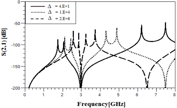
The simulated resonant characteristics are plotted in Fig. 5, where the value of Δ determines the center frequencies and two passband bandwidths. The frequency difference between two passbands also increases as Δ increases, and the larger upper passband bandwidth results as Δ increases, as shown in Fig. 5.
2. Control of Passband Bandwidths
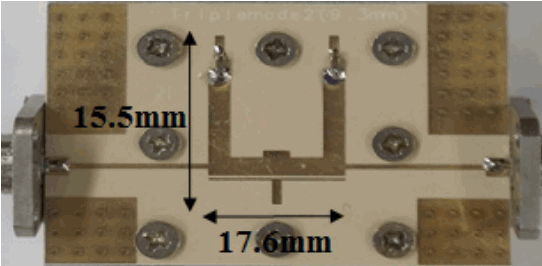
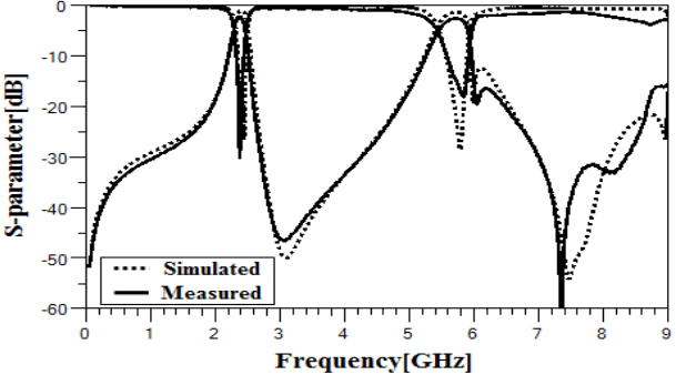
Even though we can create two passbands from the configuration in Fig. 4, the bandwidths of the two passbands cannot be determined independently. Therefore, to control the bandwidth of one passband, we added another series resonant circuit to the open-loop resonator [12, 13], as shown in Fig. 2, which can be added to either passband. The additional resonator not only determines the bandwidth but improves the skirt frequency characteristics of the corresponding passband because it increases the order of the filter by one. The additional resonant circuit also increases the passband bandwidth. Based on the above, we designed a dual-band BPF the passbands of which fall on the two Wi-Fi bands (80 MHz at 2.4 GHz band and 150 MHz at 5.8 GHz band). The filter was designed using a Duroid RO3003 substrate (εr = 3.0, tanδ = 0.0013) with a thickness of 30 mils. The line impedance of the resonator was 50 Ω and the series resonant circuits were replaced by distributed ones to reduce the insertion loss. Because of the bandwidth requirement, we designed the 2.4 GHz band as shown in Fig. 4(a) and then added a series resonant circuit, as shown in Fig. 2, to increase the bandwidth to 150 MHz. Fig. 6 shows the final layout of the proposed filter, the dimensions of which are 18 mm×15 mm. Fig. 7 shows the simulated and measured results, which show excellent agreement. The insertion loss at the 2.4 GHz band was measured to be 1.8 – 2.0 dB and at the 5.8 GHz band was measured to be 2.5 – 2.7 dB. The return loss was measured to be better than 15 dB at both passbands. The transmission zero at 3 GHz was also pronounced.
We compared the size of the proposed filter to the size of previously published ones, as shown in Table 1.
IV. Conclusion
In this paper, a novel dual-band BPF based on an open-loop resonator was proposed. By adding three series resonant circuits to the conventional resonator dual band, performances were created. Based on the proposed design procedures, a dual-band BPF working at both Wi-Fi bands was designed and tested. Because an open-loop resonator was used, the frequency response at the 2.4 GHz band was second order, while that at 5.8 GHz was third order.
Acknowledgements
This research was supported by the MSIP(Ministry of Science, ICT & Future Planning), Korea in the ICT R&D Program 2014 (B0101-14-0171).
References
Biography

Hyun-Seo Im
received a B.S. degree in electrical engineering from Soonchunhyang University in Asan, Korea in 2014 and an M.S. degree in electronic engineering from Sogang University in Seoul, Korea in 2016. He has worked for Broadcom Limited in Seoul, Korea since March 2016. His research interests include RF bandpass filters and RF system design.

Sang-Won Yun
received B.S. and M.S. degrees in electronic engineering from Seoul National University in Seoul, Korea in 1977 and 1979, respectively, and a Ph.D. degree in electrical and computer engineering from the University of Texas at Austin in 1984. Since 1984, he has been a professor in the Department of Electronic Engineering, Sogang University in Seoul, Korea. From October 2009 to October 2011, he was a project manager at Korea Communications Commission (KCC). From January 1988 to December 1988, he was a visiting professor at the University of Texas at Austin. He was the president of the Korea Institute of Electromagnetic Engineering and Science (KIEES) in 2007. He was the chairman of the IEEE Microwave Theory and Techniques Society (IEEE MTT-S), Korea Chapter. His research interests include microwave and millimeter-wave devices and systems.


