I. Introduction
Wireless power transfer (WPT) technology has attracted considerable attention in recent years due to its ease of use, high reliability, safety, and automatic accessibility to electrical power [1]. WPT can be used in applications such as medical implants [2], robotics [3], and electronic devices [4]. Given the above-mentioned benefits, the WPT system may be an appropriate alternative to wired charging systems in electric vehicles.
The static wireless charging (SWC) system has the above advantages, while the dynamic wireless charging (DWC) system, in addition to the above advantages, provides solutions to increase the range of motion, reduce size of lithium-ion battery, and eliminate waiting time for charging an electric vehicle [1].
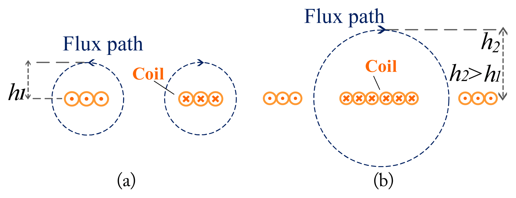
WPT systems have two coils, one acting as the transmitter coil and the other as the receiver coil. Coils can be implemented in solenoid or spiral forms. Spiral coils occupy less space (volume) than solenoid coils. Also, these coils, wound in a spiral form with increasing radius, have a much better coupling coefficient than a solenoid coil wound around a fixed radius. As shown in Fig. 1, the WPT coils were categorized into polarized and non-polarized groups. Non-polarized coils have one pole on the transmitter side and one opposite pole on the receiver side, while polarized coils have two opposite poles on the transmitter side and two opposite poles on the receiver side. The height of the flux path (h2) in polarized coils is significantly higher than non-polarized coils (h1) for a similar size. As a result, the coupling coefficient is higher in the polarized coils and is also more robust to misalignment in the horizontal direction [1], which makes the coils more appropriate for their application in electric vehicle charging in both SWC and DWC methods. Among polarized coils, the double-D (DD) design is preferred due to its simple structure, high efficiency, and low sensitivity in misalignment conditions [5]. To optimize a WPT system or estimate its operating parameters (such as received power, efficiency, and gain), the designer should accurately compute the self- and mutual inductances [6]. These computations could be carried out using analytical, numerical (finite element method [FEM]) [7], or hybrid analytical-numerical methods. The analytical method has remarkable advantages over the other methods due to its time-saving analysis and cost effectiveness. Though many studies have been carried out to compute self- and mutual inductances of WPT system coils for circular [8ŌĆō11] and square structures [12ŌĆō14], few studies have been published regarding rectangular [15, 16] and DD power coils [17]. An analytical method to compute self- and mutual inductances of spiral rectangular coils is presented in [18]. However, it is rather complicated due to its dependence on computers and the need to set initial burdensome values [6]. A numerical-analytical method based on infinite integral, infinite Bessel series, and trigonometric functions is proposed in [19] to calculate the mutual inductance between two rectangular coils, which must be resolved numerically [20]. An analytical method to calculate inductance for multi-loop spiral coils is proposed in [21] based on Grover equations [22], which for each piece of conductor, the self- and mutual inductances must be computed and added together. Applying this method to compute the inductance of multi-loop coils is time-consuming, even with fast computers [16]. In [17], the Grover-based method is used to calculate self-inductance, and the Neumann-based method is employed for mutual inductance. This method is not ideal for the computation of DD power coils in terms of computational errors. Also, since no experimental setup has been implemented, the analytical results were not validated by any experimental results.
This paper obtains self- and mutual inductances of transmitter and receiverŌĆÖs DD coils by analytically employing the Biot-Savart law, which is simpler than the abovementioned methods. For demonstration, we validated the analytical calculations using the numerical and measurement results. We also obtained the mutual inductances for various DD coil distances (coaxial) using the proposed analytical method, as well as numerical and experimental methods. According to the low error between spiral and single-loop coil inductances in the proposed method, each spiral multi-turn coil is considered a several-filament single-loop coil. Finally, we examine the optimized dimensions of the transmitterŌĆÖs coil in terms of the coupling coefficient across the coils on the condition that the dimension of the receiverŌĆÖs coil is constant.
II. Analytical Modeling of DD Coils
1. Computation of Self-inductance
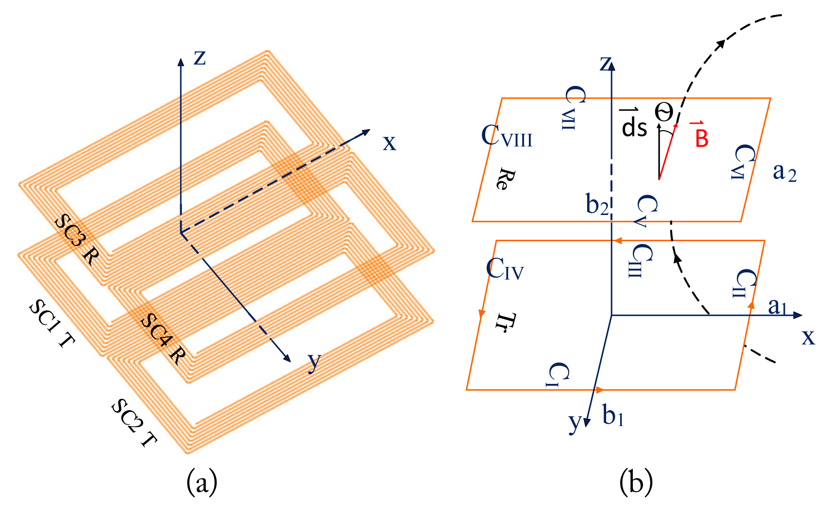
Fig. 2(a) shows a DD coil, which consists of two D-shaped spiral sub-coils and, in series form, electrically. According to Fig. 2(b) and 2(c), for simplification purposes, each spiral sub-coil is considered a several-concentric single-loop coil. According to Fig. 2(c), w is the wire diameter and s is the distance between two adjacent wires. Variables in Fig. 2(d), including the length and width of the loops, are a, b. The dimensions of the ith loop, including ai and bi can be obtained by
where i = 1 is the outermost loop.
To obtain the self-inductance of a loop, the flux enclosed by that loop must be computed and divided into the loop current. The flux of ith loop is obtained according to
where Bi is the field density, and Si is the cross-section of ith loop. According to right-hand law, the field density is perpendicular to the plane. Therefore, given the perpendicularity of the unit vector on the yz plane, according to Fig. 2(c), the internal multiplication is eliminated. Moreover, since, in this case, the largest physical dimension of coil a, relative to wavelength ╬╗, is electrically very small (i.e., a Ōē¬ ╬╗), the frequency effect of the source could be neglected [23]. Hence, Eq. (2) can be used to compute the self- and mutual inductances.
The flux density of conductor CI, in Fig. 2(d), is obtained using the Biot-Savart law according to (3). In the following, Eqs. (3)ŌĆō(6) are applied to calculate the flux density and flux caused by conductor CI, as well as the total flux of the loop, respectively [24].
R is the distance between the element and the point at which we are computing the magnetic field B, which can be defined as
where Z is the distance of the given point to the xy plane, r is the perpendicular distance of the given point to the z axis, ╬╝0 is the vacuum permeability coefficient, and I is the loop current, the value of which is considered a unit. Loop flux, caused by CI conductor current in Fig. 2(c), is computed by
To obtain the total flux of the loop (conductors CI, CII, CIII, CIV), flux caused by all four conductors should be added. Thus, the total flux of loop i caused by the current of the loop itself, is as follows:
(6)
In Eq. (6), inductance is obtained by assuming
a , b Ōē½ w 2
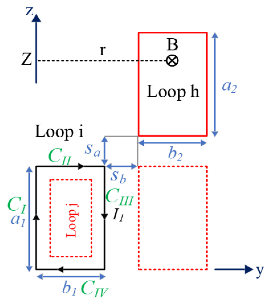
To calculate the mutual inductance of loops h or j, the flux enclosed to loops h or j should be divided on current I1 (as part of loop i):
where ╬”iŌłÆj,h is the enclosed flux to loops h or j, and I1 is the current of loop i. The enclosed flux to loops h or j is obtained according to the following equation:
where Sj,h is the plane of loop j or h, and BiŌłÆj,h is the field density. According to the right-hand law, the field density is perpendicular to the plane. As a result, internal multiplication could be eliminated. The formula for field density is obtained through the Biot-Savart law, which is similar to Eq. (3). The difference is that it is shifted toward the positive part of the z-axis (Fig. 3) as much as
a 2
(9a)
The above equation can be further compressed as
According to the right-hand law, conductors CI and CIV create imported flux, and conductors CII and CIII create exported flux on the plane of loops h or j. Therefore, the mutual inductance equation per four inductors is as follows:
(10)
Sub-coils 1 and 2 are similar; thus, by doubling Lsc1, inductance of a DD coil is obtained and is represented by LDD.
LDD self-inductance of a DD coil is analytically obtained as
where Lsc1, Msc1, and Msc1,2 are the self-inductance of sub-coil 1, the mutual inductance between loops of sub-coil 1, and the mutual inductance between loops of sub-coils 1 and 2. Using the results of Section IV, it can be inferred that section Msc1,2 of self-inductance calculations can be neglected due to its low effect on the intended response and to reduce the complexity of the calculations. Therefore, Eq. (11a) can be simplified as follows:
This formula holds true when ferromagnetic materials are not used. The proposed model can be easily developed for this case by inserting a scaling factor for ╬╝r in Eqs. (6) and (10) [9, 13].
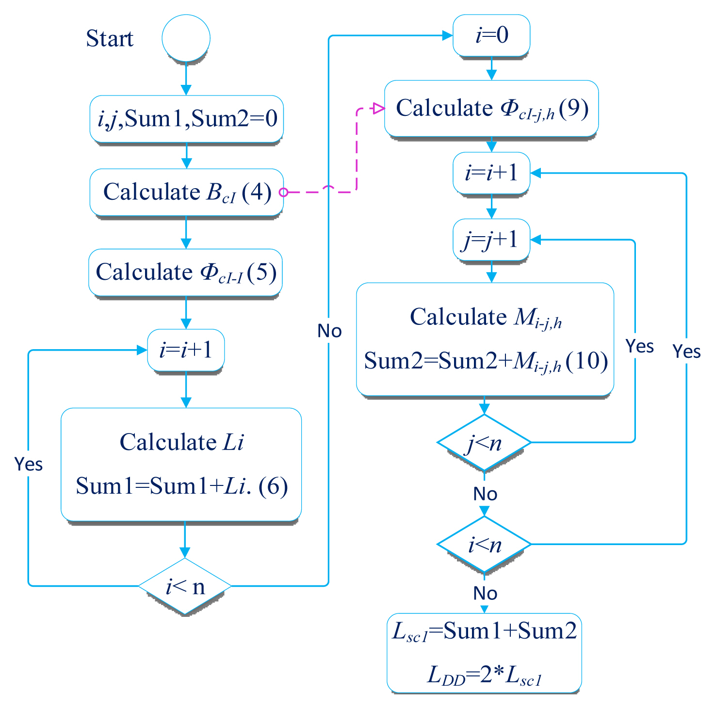
The flowchart in Fig. 4 demonstrates how the self-inductance of the transmitter and receiver coils is calculated. As observed in the flowchart, i, j, and n are symbols of loop numbers of sub-coil 1. The sum of the self-inductance of sub-coil 1 is named sum 1, and the mutual inductance between loops of sub-coil 1 is named sum 2. The total sum of sum 1 and sum 2 composes the self-inductance of sub-coil 1 and is presented by Lsc1 in the relevant flowchart. Sub-coils 1 and 2 are similar; thus, by doubling Lsc1, the inductance of a DD coil is obtained and is represented by LDD.
2. Computation of Mutual Inductance
The DD coils of the transmitter and receiver are shown in Fig. 5(a). Given the above explanation in Section II-1, DD coils consist of a Litz conductor. Moreover, since the operating frequency of these systems is normally less than 100 kHz, the skin effect is negligible here and filamentary is logical. Also, each sub-coil is considered a several-concentric filamentary single-loop. The outer loops of sub-coils 1 and 3 of DD coils are shown in Fig. 5(b). The formula of mutual inductance for DD coils is then computed by
where Msc1,3, Msc2,4, and Msc1,4, Msc2,3 are mutual inductances of the facing sub-coils and mutual inductances of non-facing sub-coils in DD coils, respectively. According to the investigation presented in Section IV, since the mutual inductance value is insignificant in non-facing sub-coils, they are neglected to avoid computational complications. Hence, Eq. (12) is simplified as
The mutual inductance between ith single-loop (transmitter) and uth single-loop (receiver), according to Fig. 5(b), is obtained from the division of flux of uth loop to the current of ith loop as
Then, the flux of uth loop is calculated from
Biu is the field density caused by the conductor CII, and Su is the plane of uth loop. Also, the point here represents internal multiplication. ╬Ė is the angle between the unit vector of the plane of uth loop and the vector of Biu field density (Fig. 5(b)). According to the Biot-Savart law, the equation of field density along the z-axis is as below. Eqs. (16) and (17) are the flux density and flux (or mutual inductance) of conductor CII [20].
Also, magnetic flux caused by conductor CII along the z-axis, which is the effective component for computing mutual flux, is obtained by
(17)
According to Fig. 5(b), a1, b1, a2, and b2 are the dimensions of the transmitterŌĆÖs and receiverŌĆÖs loops, and z is the distance between two loops along the z-axis. Given the conductorsŌĆÖ symmetry, ╬”CI =╬”CIII and ╬”CII=╬”CIV are equal. To obtain the magnetic field of the conductor ╬”CII in Eq. (17)a1 and a2 should be replaced with b1 with b2, respectively. According to right-hand law, the general formula of the magnetic field is equal to ╬”iu=╬”CI +╬”CII +╬”CIII +╬”CIV. The general mutual inductance is obtained as
where i and n are loops of sub-coil 1; h and m are loops of sub-coil 2; u and v are loops of sub-coil 3; and w and x are loops of sub-coil 4. This formula holds true when ferromagnetic materials are not used. The proposed model can be easily developed for this case by inserting a scaling factor for ╬╝r in Eqs. (18) [9, 13].
III. Finite Element Modelling of DD Coils
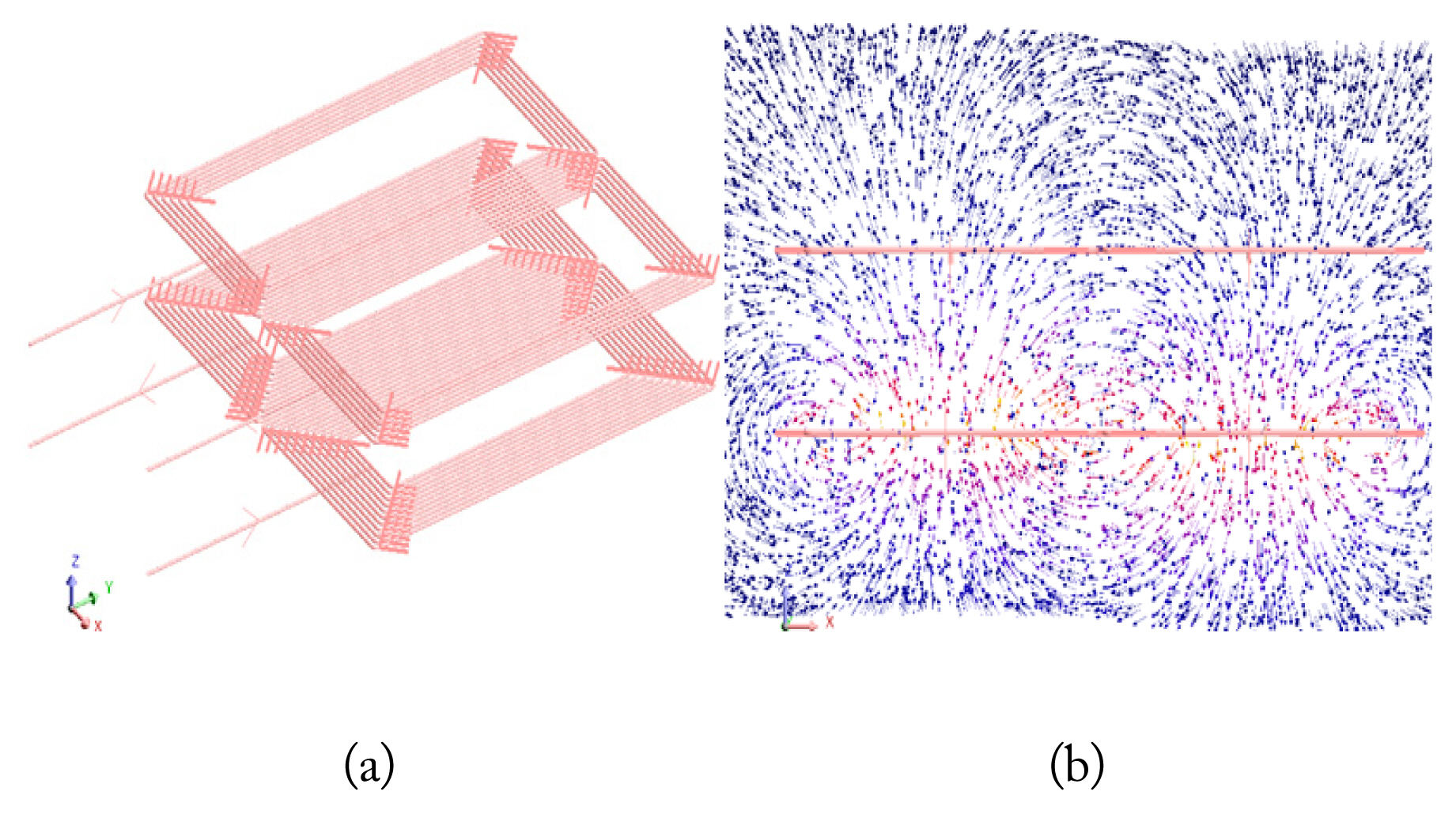
The FEM model was developed in Altair Flux3D to confirm the proposed analytical model and obtain the magnetic parameters of LDDT, LDDR, M, and k. The model is designed based on the parameters given in Table 1.
Fig. 6(a) shows the 3D-FEM model of DD coils, and Fig. 6(b) represents the coilŌĆÖs magnetic flux path. According to Fig. 6(a), in the FEM simulation, each transmitter and receiver consists of two sub-coils. Each sub-coil consists of 11 transmitter coil and 6 receiver coil separate conductor loops. After building the transmitter separate loops in the FEM simulation, all the transmitter loops are assigned to one coil (transmitter coil); therefore, all the loops are electrically in series. The same is true for the receiver coil. The coils in the FEM simulation are like the prototypes considered in the analytical model as well as the experimental prototype; however, the difference is that the analytical case does not have rounded corners, and FEM and analytical simulations, compared to the experimental prototype of DD coils, are considered separate loops instead of spirals. Using the FEM simulation, the coils were modeled into spirals and separate loops, and the errors for LDDT, LDDR, and M, are 0.25%, 0.5%, and 0.77%, respectively.
1. Coupling Coefficient Optimization
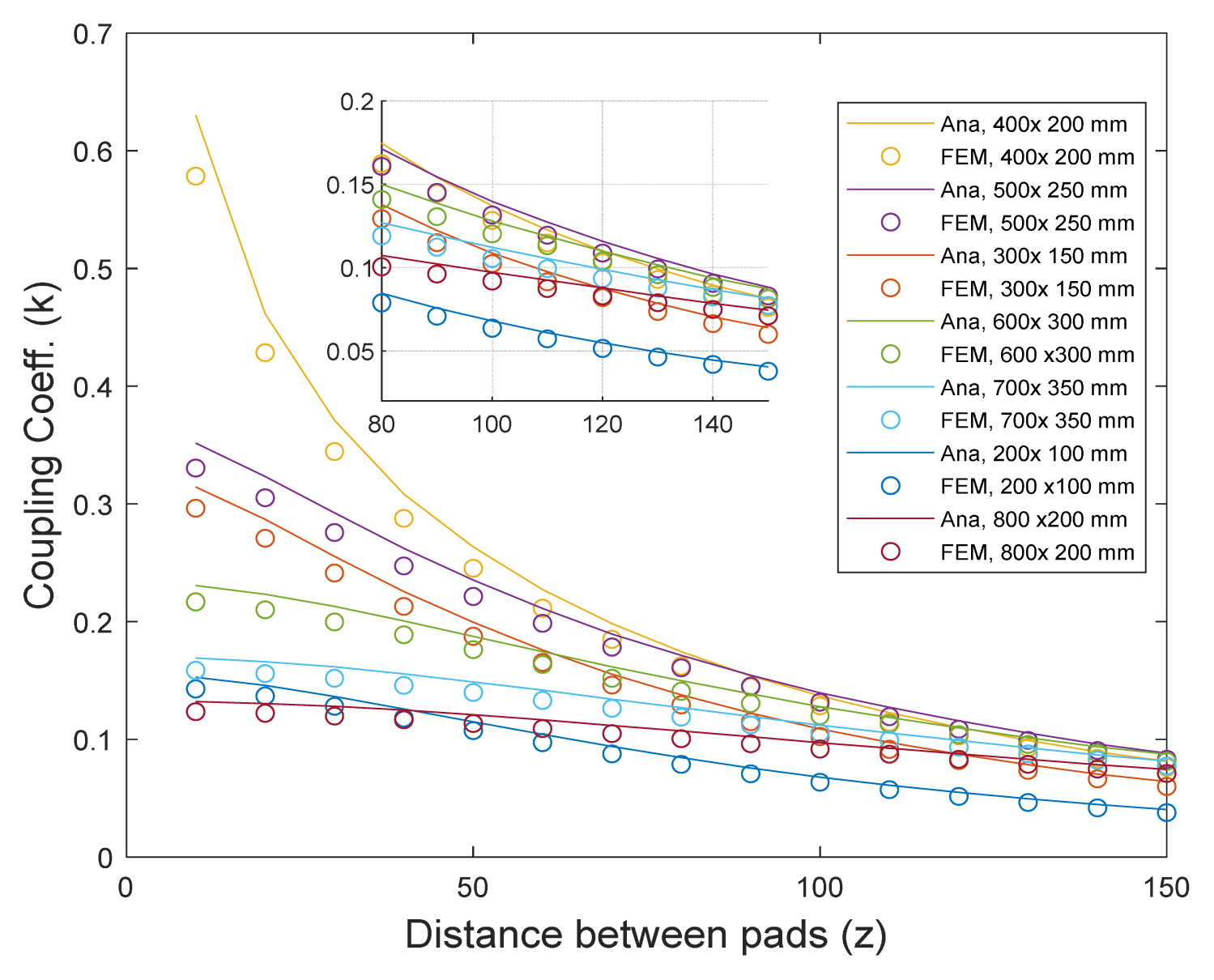
In some applications of the WPT system, such as medical implants, cell phones, and robotics (UAV), the receiver coil has some limitations in terms of dimensions and weight. In electric vehicle applications, the receiver coil has a definite and specified size according to the SAE J2954A standard [37]; however, the transmitter coil normally does not have any restrictions in dimension and weight. Hence, by changing the dimensions of the transmitter coil, the coupling coefficient and efficiency can be improved. Given the intended approximations for calculating self- and mutual inductances in this paper, a DD coil might be composed of several rectangular loops. The effect of the dimension change of a loop from the transmitter loop relative to constant receiver loop dimensions on the coupling coefficient is investigated using the analytical and FEM methods shown in Fig. 7.
According to the results in Fig. 7, the highest coupling coefficient occurs at a distance of 10 < z < 100 mm between the transmitter and receiver loops in the case that they are similar (400 ├Ś 200 mm). From a 100 < z < 150 mm distance between loops, a transmitter loop with a dimension of 500 ├Ś 250 mm creates the highest k. Also, at a distance of z > 150 mm, the transmitter loop with 600 ├Ś 300 mm dimensions has the highest k.
Consequently, according to the results in Fig. 7, in low distances between the two loops, equal dimensions of the transmitter and receiver loops result in an optimal state. By increasing the distance between loops and the dimensions of the transmitter loop, the optimal coupling coefficient is achieved.
IV. Experimental Results and Coupling Coefficient Optimization
1. Self-inductance Measurement
An experimental setup was implemented to investigate the accuracy of the analytical method for obtaining the self- and mutual inductances of DD coils (Fig. 8). Table 1 presents the specifications of the coils. In this research, the RLC meter, Lutron LCR-9184 model (Lutron Electronic Enterprise Co. Ltd., Taipei, Taiwan) is employed to measure self- and mutual inductances of DD coils.
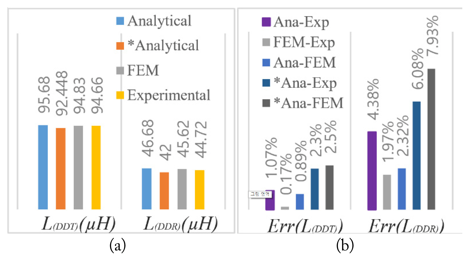
Fig. 9 shows the results of the self-inductance of the transmitterŌĆÖs and receiverŌĆÖs DD coils when applying the analytical, FEM, and experimental methods. From the results shown in Fig. 9(a), comparing the numbers obtained for self-inductance through the abovementioned methods (without approximating the elimination of the mutual inductance between two sub-coils of a coil Msc1,2 or Msc3,4) proves that the occurred errors are very small, such that the maximum result error is 4.38% (Fig. 9(b)). According to the analytical results marked by a star in Fig. 9, it could be observed that by neglecting mutual inductance between sub-coils 1 and 2 in the transmitter coil (Msc1,2) or between sub-coils 3 and 4 in the receiver coil (Msc3,4) for the self-inductance calculation (for simplification), the maximum error between the analytical-experimental results is 6.08% and between the analytical-simulation is 7.93%, which is acceptable.
To show the performance of the proposed method, we compared the self-inductance of a loop of one sub-coil and one loop of a DD coil with the findings in [17]. As shown, the results of FEM-EXP and ANA-EXP in the proposed method for a single loop of a sub-coil and DD coil are significantly better than those of [17].
To investigate the accuracy of the formula and approximations for obtaining mutual inductance between DD coils, we developed the experimental prototype shown in Fig. 8(b), which uses an RLC meter connection to obtain MDD. To measure mutual inductance, one can act as shown in Fig. 8(b).
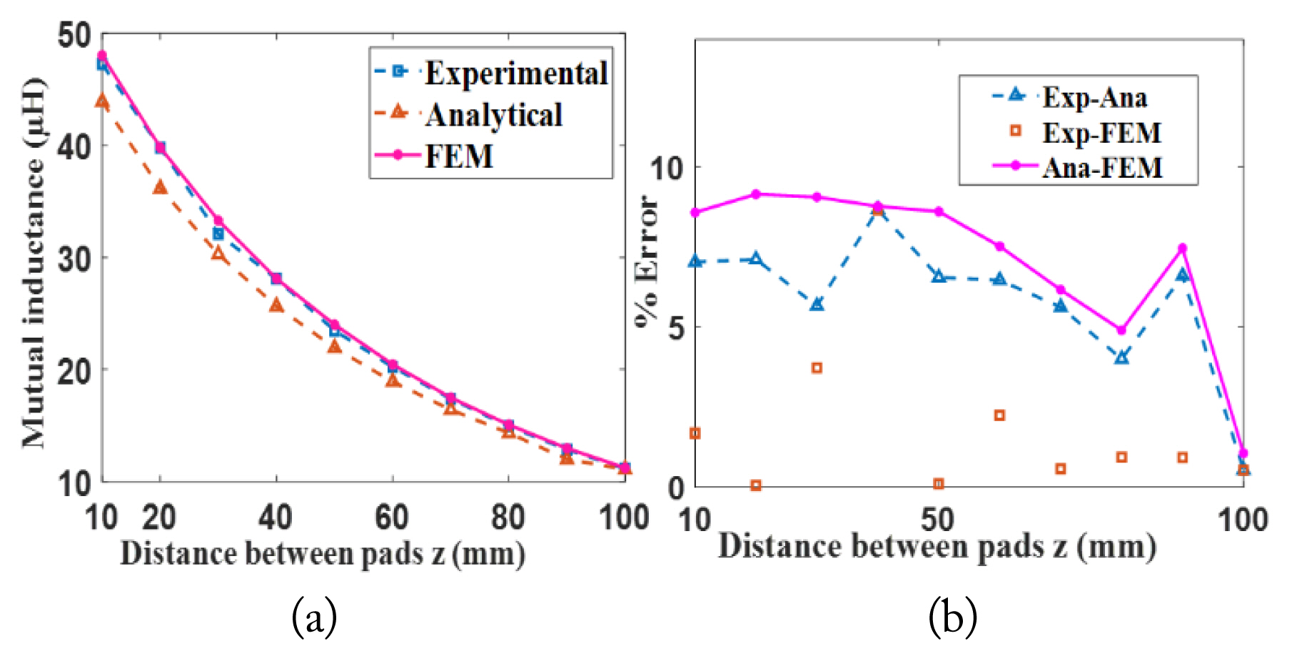
Fig. 10(a) shows the computation results of the mutual inductance between the transmitter and receiver DD coils with a distance of 10ŌĆō100 mm between the two coils, obtained using the analytical, experimental, and FEM simulation methods. As shown in Fig. 10(b), the maximum error of the mutual inductance between the two coils in the analytical-experimental, simulation-experimental, and analytical-simulation methods are 9.12%, 8.68%, and 9.16%, respectively, which occurs in very small air gap between the two coils. As the distance between the transmitter and receiver coil increases, the chance of computational error reduces, such that with a 100-mm distance between two coils, the error values for the analytical-experimental, simulation-experimental, and analytical-simulation methods are 0.54%, 0.54%, and 1.06%, respectively. The error value observed in the results of mutual inductance MDD is caused by an approximation of the neglected mutual inductance in non-facing sub-coils, error measurement, and errors caused by considering a spiral coil in several concentric filamentary single-loop forms.
2. Comparison of the Simulation and Proposed Analytical Model
Table 2 shows a comparison of the computation times for the Altair Flux3D and the proposed analytical model (MATLAB) to obtain self- and mutual inductances. The simulations were executed on an Intel Core i7-7500U CPU with a processor 2.7 GHz clock speed and 12 GB RAM (Asus K541U). The comparison confirms that the use of the proposed analytical model saves significant computational time.
Also, by disregarding Msc1,2 and Msc3,4, the number of iterations of the equations (calculate LDDT) will decrease from 484 to 242; as a result, the computation time will be reduced to 0.13 seconds.
V. Conclusion
This paper presented an analytical computational method for the self-inductance of two DD coils and mutual inductance. Analytical computations, FEM, and experimental results of self- and mutual inductances were obtained and compared. The proposed method is simpler than existing methods. The findings showed that the elimination of Msc1,2 and Msc3,4 in the calculation of self-inductances and Msc1,4 and Msc2,3 in the mutual inductance calculation reduces the complexity of analytical calculations but does not considerably affect the proposed method accuracy. The optimization of the coupling coefficient on the transmitter coil was performed in applications where the receiver coil had a size or weight limit. Table 3 also proves the accuracy of the results of the proposed method compared to the existing literature. An analytical model could be applied to design and optimize the DD coils of a WPT system; nonetheless, it does not have the problems of 3D-FEM, such as being time-consuming and costly. The proposed method could be extended to calculate self- and mutual inductance for the computation of various chargersŌĆÖ coils, such as DD, DDQ, BP, QD, and extended DD, which are appropriate for DWC application.